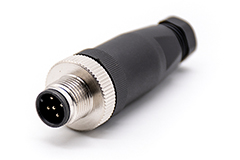
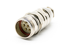
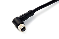
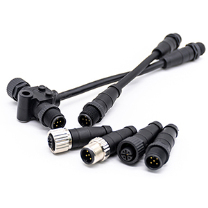
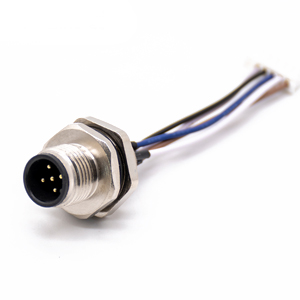
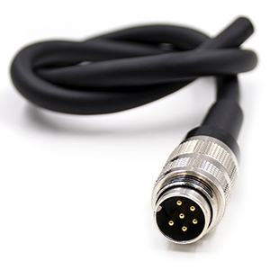
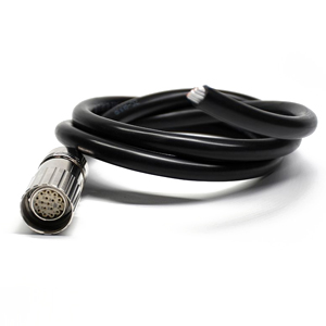
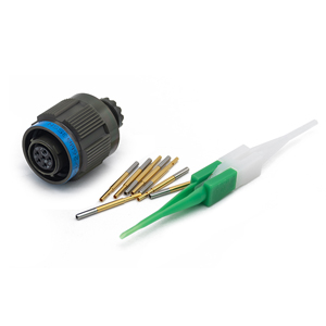
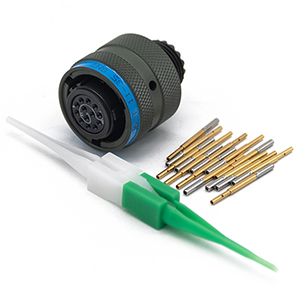
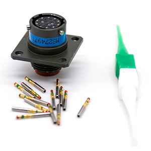
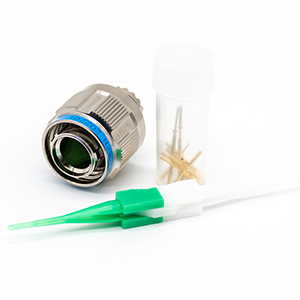
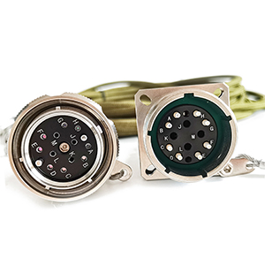
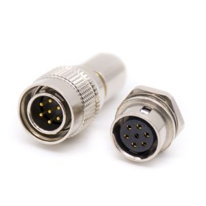
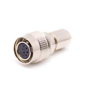
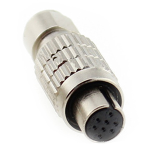
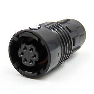
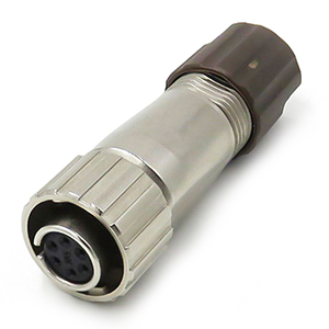
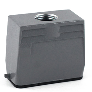
M Series Connectors
Are lightweight triplestart ratchet coupling type connectors designed for avionics, aerospace, Harsh Environment Connectors, security, motorsport and heavy duty applications.
The high voltage interlock function is also an important function on the BMS, and other high voltage controllers will also have this function, such as VCU. Its function is to detect the connection status of the high voltage interlock connector in the high voltage circuit and identify the fault of unconnected or accidental disconnection of the high voltage connector.
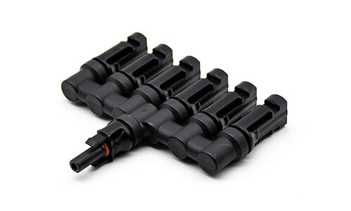
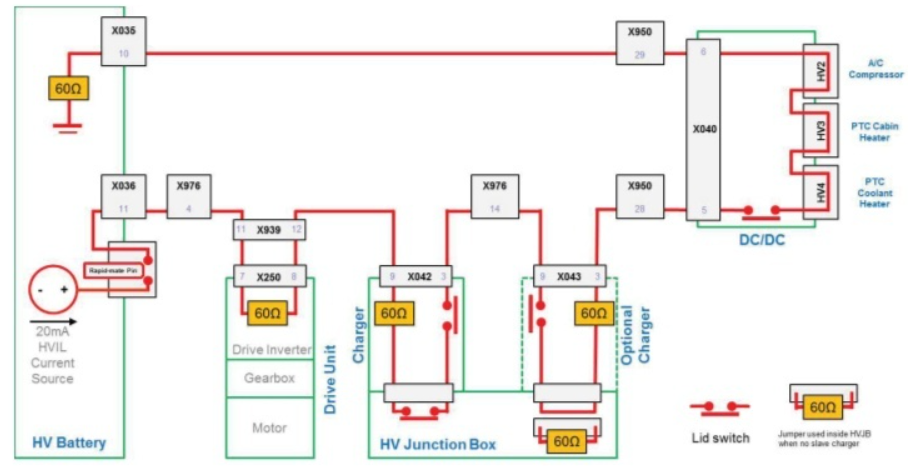
As shown in the figure below, the loop of the red line in the figure is the high-voltage interlocking loop, which connects all the relevant high-voltage connectors in the system in series and detects their connection status at the same time.
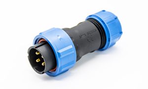
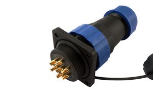
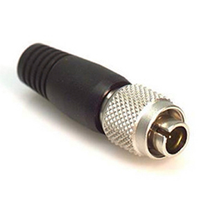
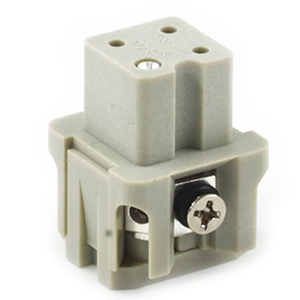
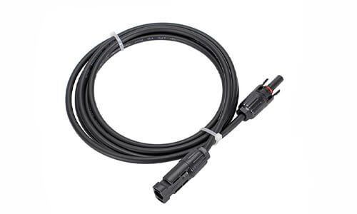
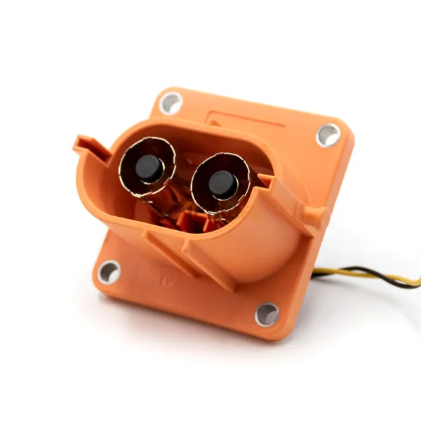
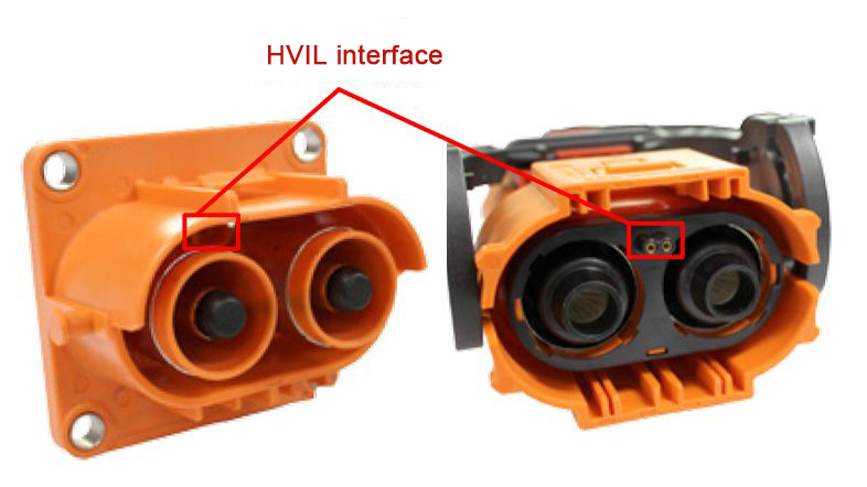
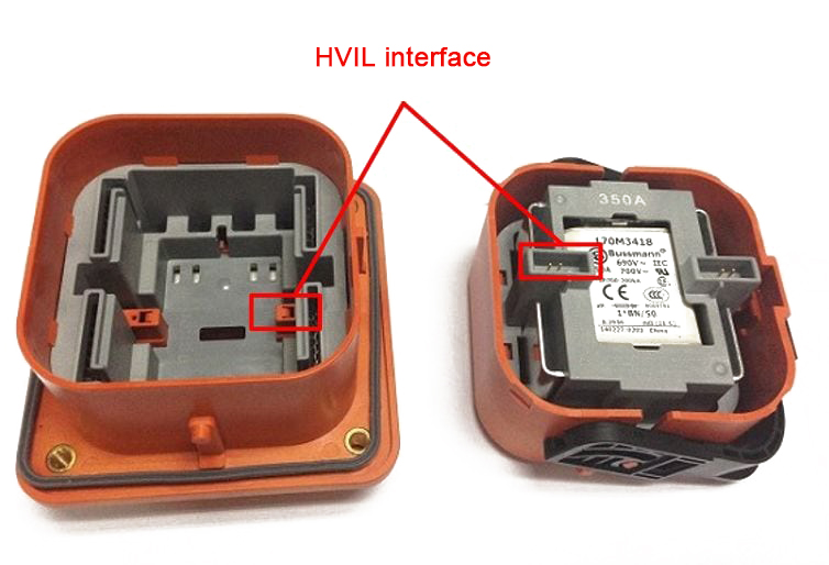
The implementation of HVIL depends first on the structure of the connector itself. As shown in the figure below, the HVIL interface is integrated into the high-voltage connector in addition to the high-voltage and high-current interface.
The principle is simple. The HVIL interface has two PIN pins. The HVIL function works by detecting the on/off of these two PIN pins.
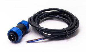
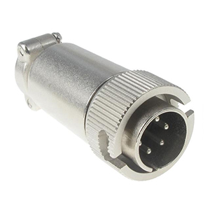
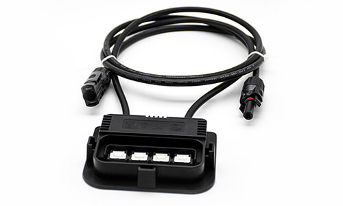
Similarly, the high-voltage maintenance switch (MSD) also integrates the HVIL interface, as shown in the figure below.
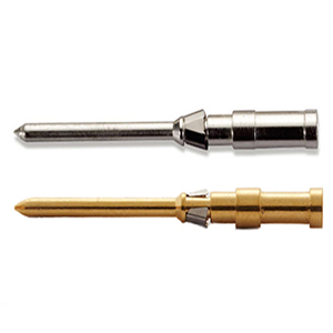
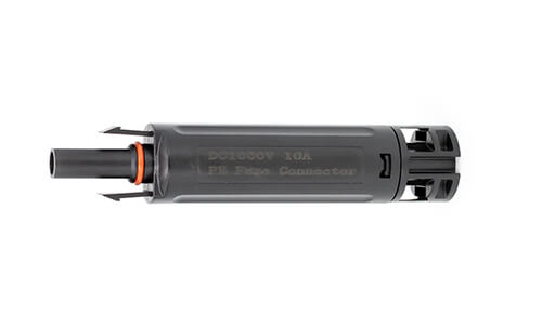
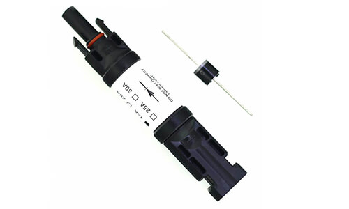
When inserted or unplugged, there is a time difference between the HVIL interface and the high-voltage high-current interface in the high-voltage connector. As shown in the figure below, when the connector inserts, the HVIL terminal contacts first, and the HVIL terminal contacts later. The time difference is Δt1; when the device unplugs, the HVIL terminal disconnects first, and the HVIL terminal disconnects later, and the time difference is Δt2.
This way, HVIL terminals can ensure that high-voltage terminals have a reliable connection or that unexpected disconnections can occur in anticipation.
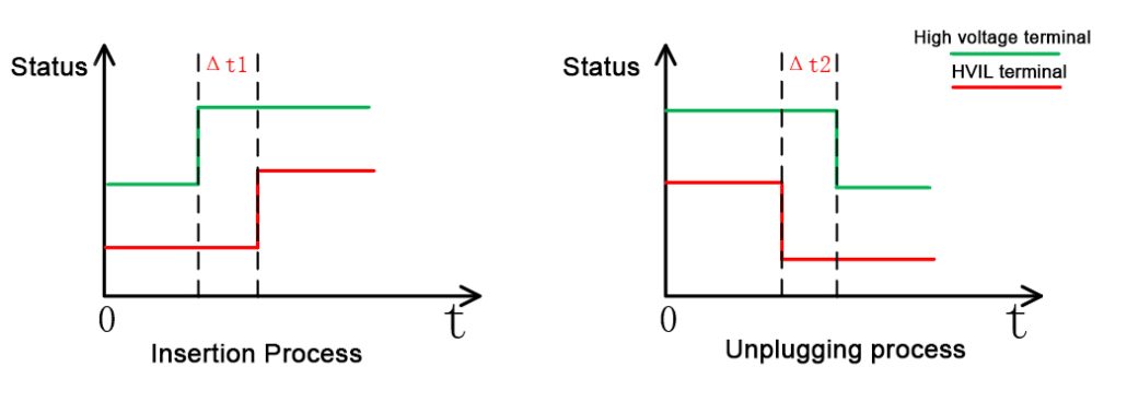
The above two time differences are generally related to the speed of insertion or removal. Δt1 is about 1 s, and Δt2 is about 100 ms. The time is inaccurate, but the magnitude is about the same.
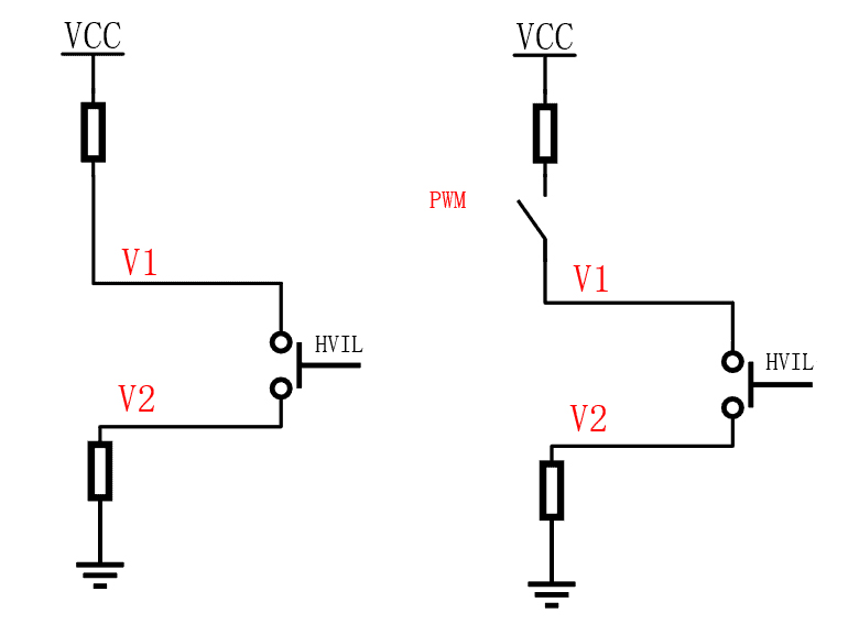
Next, a brief introduction, the HVIL detection circuit is generally divided into two types, the DC source scheme, and the PWM scheme.
As shown in the figure below, the left figure is a simplified diagram of the DC source scheme. And the right figure is a simplified diagram of the PWM scheme. In the left diagram, an external DC source is applied to the entire HVIL circuit to diagnose the state of the high voltage connector by detecting the voltage at V1/V2. Similarly, the right diagram presents a controlled switch, again still detecting the voltage at V1/V2. Still, by controlling the switch, it is possible to obtain two sets of values to identify more states.
The actual HVIL detection circuit is more complex. First, you must determine the type of fault to detect and then design the detection circuit based on the fault type. Fault types include open circuit, short to ground, short to power, and high circuit impedance.
High voltage interlock diagnosis is an important safety mechanism and belongs to the safety objective of the BMS. In the event of a failure, the BMS must go into a safe state. Among other things, the whole vehicle scenario needs to take a breakdown. The safety state is completely different in different scenarios, e.g., charging, driving, starting, etc.
In this paper, the concept of HVIL is briefly introduced. In most cases, the HVIL circuit is a system circuit. It traverses all major high voltage interfaces, and it is up to the OEM to define the detection range. The difficulty of the HVIL function lies in the handling strategy after fault detection, which is the core.
As an industry specialist at Renhotec Group, I have years of expertise in the field of electronic interconnection. Founded in 2008, Renhotec Group is a global leader in designing and manufacturing connectors, cables, and custom electronic components for a wide range of industries. We are committed to providing high-performance interconnect solutions, leveraging technical innovation and rigorous quality standards to empower global customers across industrial, RF, and EV sectors.