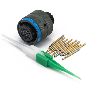
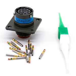
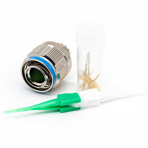
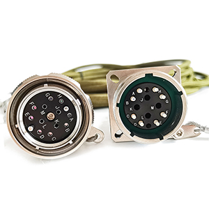
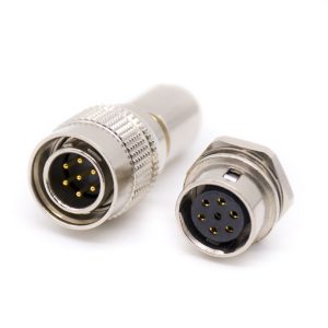
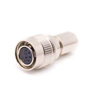
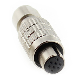
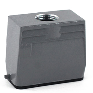
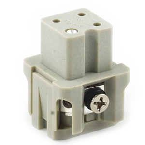
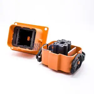
M Series Connectors
Are lightweight triplestart ratchet coupling type connectors designed for avionics, aerospace, Harsh Environment Connectors, security, motorsport and heavy duty applications.
Definition of high voltage interlock: Check the integrity and continuity of the loop of the entire high-voltage system through the low-voltage signal, identify the abnormal disconnection of the loop; and disconnect the control electrical components of the high-voltage input in time.
Scheme 1 is shown in Figure 1. The thick solid line represents the 12V low-voltage power circuit in the detection circuit, and the dashed line represents the HVIL monitoring circuit.
The HVIL monitoring circuit of high-voltage components (DCDC, PTC, compressor, etc.) is controlled by VCU, and the low-voltage control output terminals of the three high-voltage relays in the battery pack are directly grounded through detection point 1 to monitor the working condition of the emergency power-off circuit.
The high-voltage HVIL circuit of the motor and DCU is directly connected to the control coil of the low-voltage relay 2, and the other end is grounded.
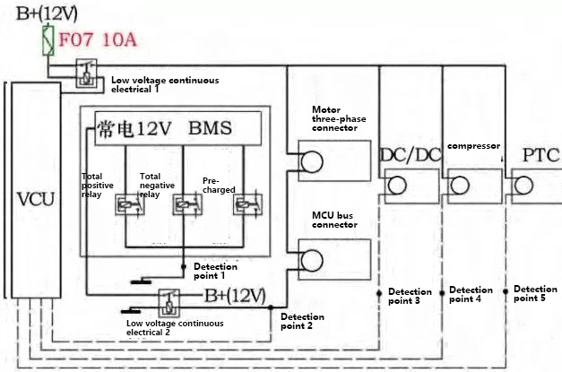
In the event of an emergency power failure, monitoring point 1 feeds the detection directly to the BMS, which disconnects the three high voltage relays.
When the motor is connected to the high voltage connector of the DCU, low voltage relay 2 is opened and the BMS is switched on to 12V. When the high voltage connector is not connected, the power supply to the BMS is disconnected via the low voltage relay 2, enabling the power failure function.
Other high-voltage components detect their respective HVIL states through detection points 3, 4, and 5, and feed them back to the VCU.
Each high-voltage component has its own HVIL test, if a fault occurs, it is easy to troubleshoot. The HVIL status of the motor and DCU can directly determine whether the BMS is working and reduce the risk.
The disadvantage is that the low-voltage relay is added to control the BMS power supply, which makes the wiring harness design more complicated, and the total weight of the wiring harness increases.
In addition, if the low-voltage relay 2 is stuck, the VCU can only pass the BMS and Indirectly disconnect high-voltage components.
In the second scheme (as shown in Figure 2), the thick solid line represents the 12V power line, and the dotted line represents the HVIL detection circuit.
Compared with the first scheme, except for the motor and DCU, other high-voltage components are connected in series, and only one monitoring point is needed. In addition, the low voltage relay 2 is missing.
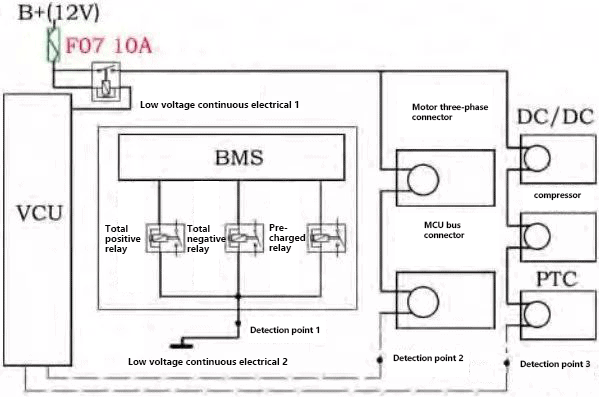
When encountering an emergency power failure, detection point 1 sends the detection result directly to the BMS, and the BMS directly disconnects the high-voltage relay; the motor and DCU detect the connection of the high-voltage connector through detection point 2 and send it to the VCU.
If any connector is not properly connected, the VCU detection result controls the BMS, which makes the BMS control the high-voltage relay action to achieve power-off.
The HVIL status of the other three high-voltage components is determined by monitoring point 3. If one is not connected, the VCU disconnects the high-voltage relay by controlling the BMS.
Compared with solution one, solution two has advantages in wiring harness design and wiring harness quality. But if there is an abnormality in detection point 3, it is difficult to determine which high-voltage component has an abnormal HVIL.
___
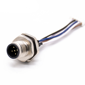
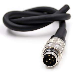
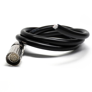
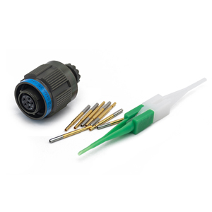
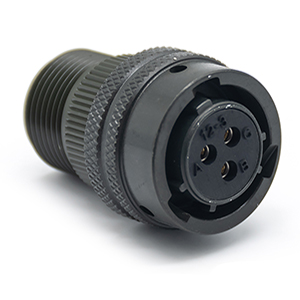
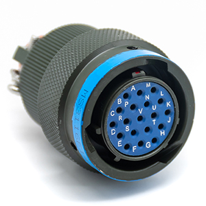
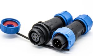
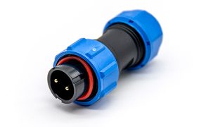
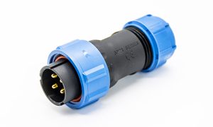
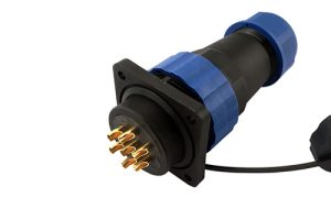
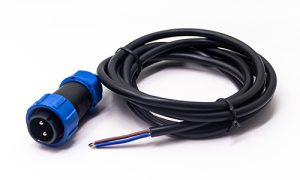
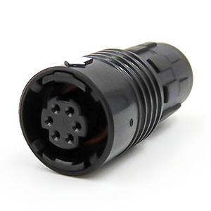
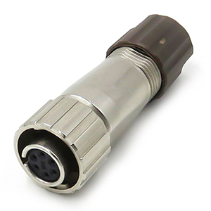
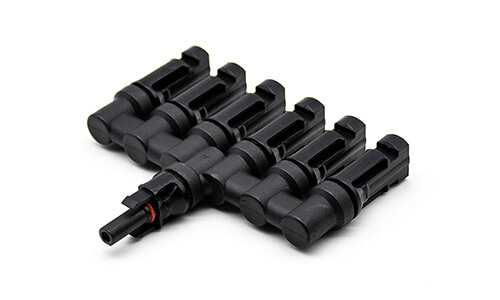
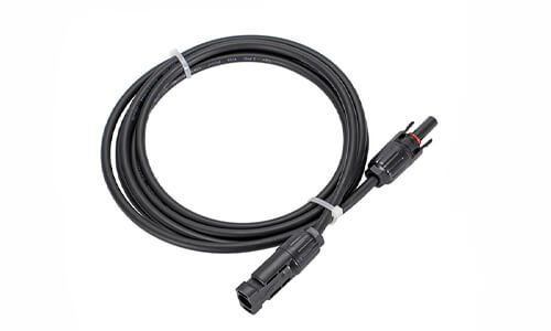
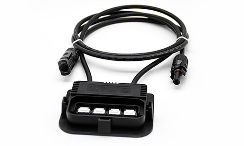
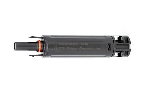
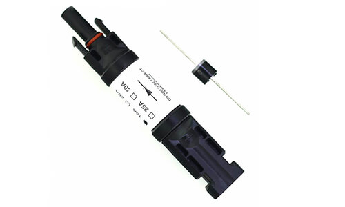
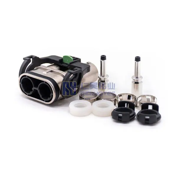
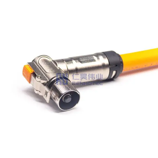
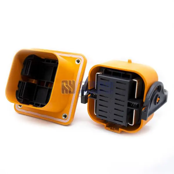
Related Products
As an industry specialist at Renhotec Group, I have years of expertise in the field of electronic interconnection. Founded in 2008, Renhotec Group is a global leader in designing and manufacturing connectors, cables, and custom electronic components for a wide range of industries. We are committed to providing high-performance interconnect solutions, leveraging technical innovation and rigorous quality standards to empower global customers across industrial, RF, and EV sectors.