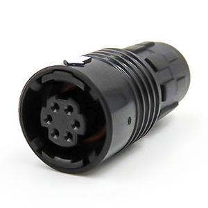
Are lightweight triplestart ratchet coupling type connectors designed for avionics, aerospace, Harsh Environment
Connectors, security, motorsport and heavy duty applications.
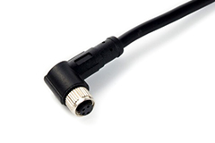
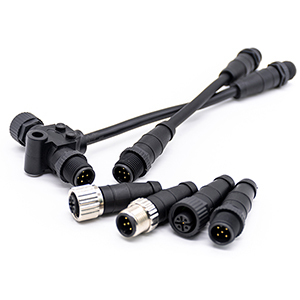
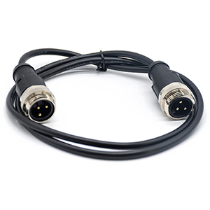
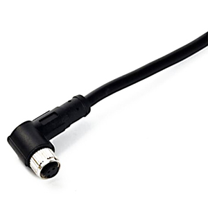
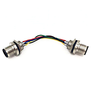
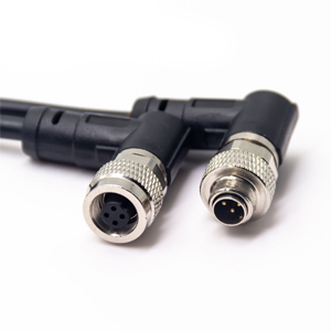
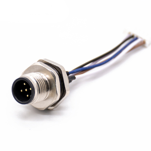
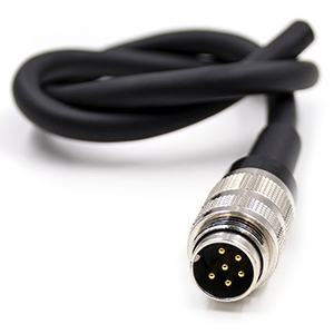
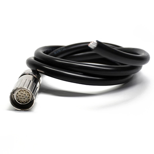
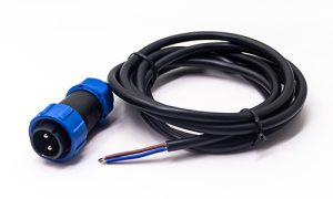
Circular Cable Assemblies
A circular cable assembly consists of a section of cable material with a circular connector at one or more
endpoints.
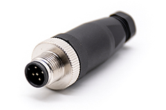
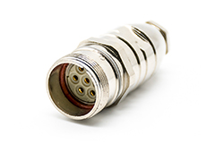
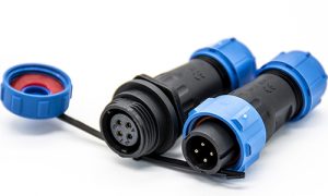
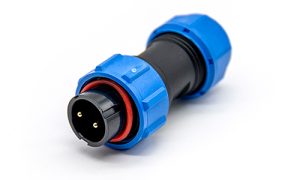
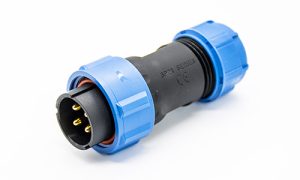
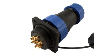
Renhotec offers a wide range of circular connector cable assemblies, especially M8, M12, and M16 cable assembly.
View all Circular Cable products >>
This series of connectors is an alternative solution to Lemo connector which are used in medical, industrial,
audio/visual, telecommunications, Harsh Environment Connectors, scientific research and measurement
applications.
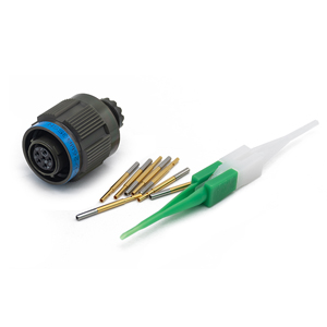
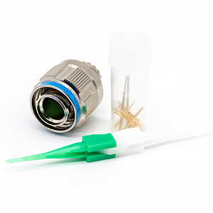
D38999s are popular and widely used subminiature circular connectors for Harsh Environment Connectors and
aerospace
applications. With three coupling methods, nine shell sizes, and a wide variety of contact arrangements, our
MIL-DTL-38999 connectors help give you the range of choices you need.
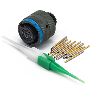
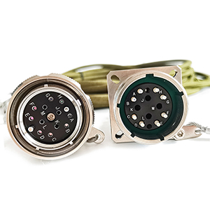
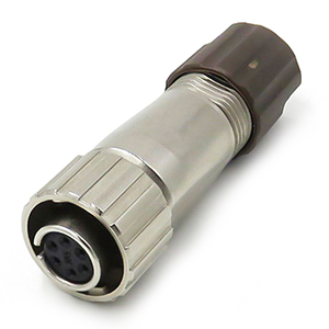
MIL-DTL-26482 connector, also known as the MIL-C-26482 connector. It boasts a wide array of pin configurations
and
can withstand high current loads. The series features heavy-duty connectors with solder contacts and bayonet or
“quick-disconnect” coupling.
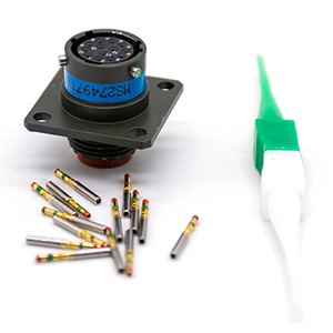
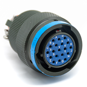
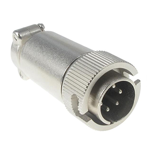
MIL-DTL-83723 Connectors also known as MIL-C-83723. This series features high-density circular connectors with threaded or bayonet coupling for aerospace.
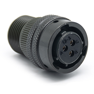
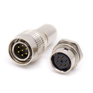
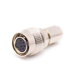
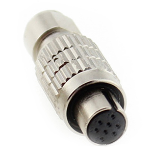
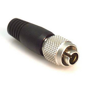
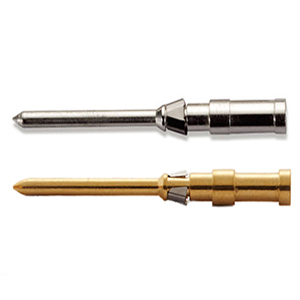
HR connectors are a lower-cost version, yet still provide a high "Value Add" while preserving the superior
characteristics of the HR connectors. Cable clamps are crimped using a special crimping tool, and the shells
have a
rubber boot which provides a flexible design that helps to prevent cable twisting.
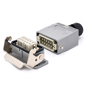
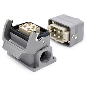
Heavy Duty Connectors (HDC) are robust industrial connectors for power, data, and signals in harsh environments.
They
offer reliability with aluminum or thermoplastic covers and IP65 to IP69k protection ratings, handling currents
from
10A to 80A and up to 216 contacts.
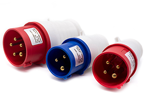
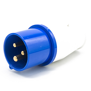
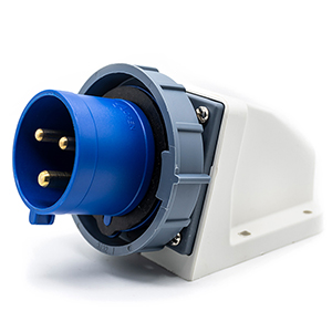
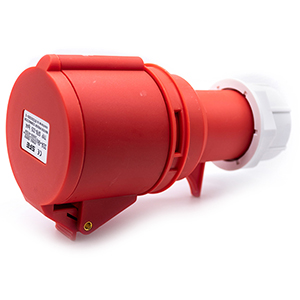
Renhotec provides a diverse range of durable industrial plugs, sockets, and related products designed to meet IEC
60309-1 standards for reliable connections in industrial and factory applications. Industrial plugs and sockets
have
3 Pin, 4 Pin and 5 Pin.
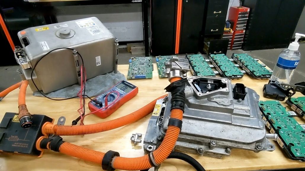
General Requirements for High Voltage Interlock Circuit HVIL
In the near future, I will pay more attention to the issue of battery high voltage safety. Here are some requirements for high-voltage interlocking. These requirements are general requirements. For these requirements, each manufacturer will have its own different implementation methods. For example, if the barrier/enclosure allows direct access, it can only be opened or removed with tools or maintenance keys, or there is some way to cut off the B-level voltage with some points, such as interlock.”
Interlock here generally refers to High Voltage Interlock Loop (HVIL), which detects the electrical integrity or connectivity of high-voltage components, wires, and connectors through low-voltage circuits that recognize abnormal disconnection of the circuit and disconnect the controller at the high-voltage input in time. When HVIL fails, ensure that the high-voltage system is safely powered off in a suitable way. Before the fault is removed, the high-voltage system cannot be powered on and the corresponding DTC is triggered at the same time.
When the high-voltage module is disconnected from the high-voltage circuit, pay attention to the Capacitive loads and high-voltage cables are charged to prevent electric shocks to operators. During normal vehicle operation, prevent electric shocks caused by improper operation, vehicle vibration, product aging, and local heating and arcing caused by line wear.
The functional safety level of HVIL-related modules in the controller should reach ASIL C
HVIL should include a signal generator and 2 signal detection devices
It must be able to continuously and real-time monitor the on/off of the entire loop
All high-voltage connectors of the HVIL circuit cannot be opened or separated without the use of tools or unconsciously
All high-voltage connectors of the high-voltage circuit should have mechanical interlocking devices. The high-voltage connectors can only be opened when the HVIL circuit is disconnected first.
The HVIL circuit should have a safety redundancy design, that is, the failure of a key component will not seriously affect the misjudgment of the high-voltage circuit monitoring function
Under special circumstances, the HVIL circuit can be detected directly through the HCU or BMS, and the high-voltage circuit can be directly disconnected.
Diagnostic Function Requirements
The HVIL-related controller should diagnose the following faults:
The circuit is disconnected
Short circuit to ground
Short circuit to 12V power supply
Short circuit
The loop impedance becomes larger
Signal Source Requirements
HVIL signal source voltage is generally 5V
HVIL and 12V power supply are short-circuited, the signal source cannot fail, and it has reverse protection
The HVIL wiring harness cannot have branch crimp contact points
When the voltage of the 12V lead-acid battery drops, such as about 10V, it is also necessary to protect the HVIL signal source to have a stable output.
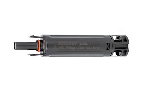
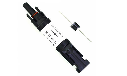
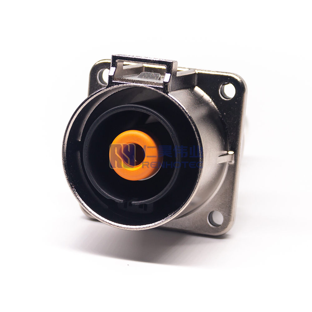
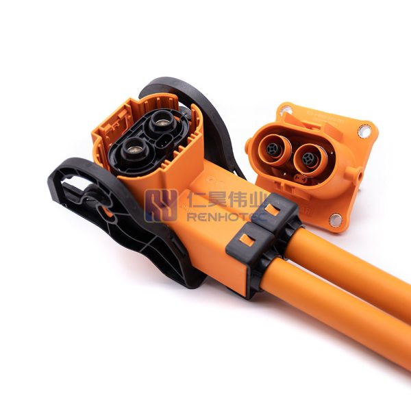
High Voltage Connector Requirements
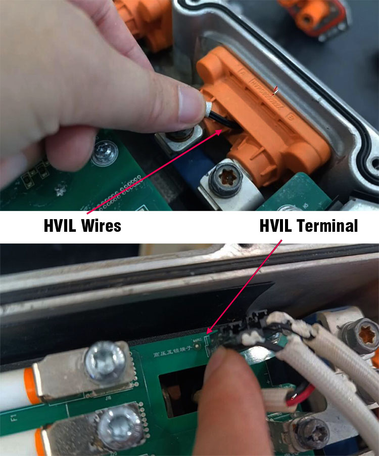
The high voltage connector needs to integrate the interlock function
When the high voltage connector is disconnected, HVIL is disconnected first; when connected, HVIL is connected later, some designs are connected at the same time
The contact resistance of the high-voltage connector after joining meets the “Technical Conditions of Automotive Wire Harness Connectors”
When the interlocking wiring harness is arranged, it should be led out from the low-voltage interface of the high-voltage components and separated from the high-voltage wiring harness.
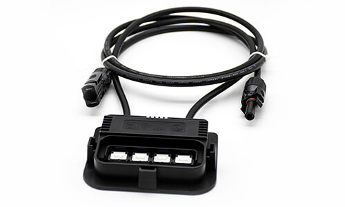
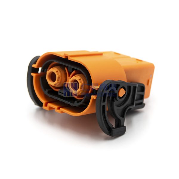
Connectors are usually crimped, plugged, and unplugged, and the angle is generally 90° or 180°, usually with built-in interlocking shorting tabs or pins at the harness end or plug-in end. For example, the picture below is the HVIL design (yellow dashed frame) in an MSD that is relatively common now, which uses pins.
When HVIL recognizes a danger, the entire controller needs to use safety strategies reasonably according to the driving status and the degree of damage caused by the accident at the time of the incident. Here are some common safety strategies:
Failure alarm. Regardless of whether the vehicle is driving or not, when HVIL recognizes a danger, it must issue a warning in some form to remind the driver to deal with it in time
Cut off the high voltage. When the vehicle is in a stopped state, when HVIL detects danger, it needs to tell the system controller to disconnect the high voltage.
Reduced power operation. When danger is identified during driving, the high voltage cannot be disconnected immediately. First, a reminder or alarm is issued to let the driver know that the abnormality has occurred, and then the control system reduces the operating power of the motor and the speed of the vehicle so that the high-voltage system works at a smaller load for the driver Provide a certain amount of time to pull over and stop for the next step of failure analysis.
There are many ways to realize HVIL in electrical design, and the realization of each way needs to consider the interrelationship between various high and low voltage devices, and comprehensively consider the overall requirements of the system.
One thought on “General Requirements for High Voltage Interlock Circuit HVIL”
Jovana says:
Hello,
Is there now an solution other than HVIL in the connectors? I am talking about HV automotive connectors. Now there are some connectors that don’t have HVIL implemented and I got to know why.


Hello,
Is there now an solution other than HVIL in the connectors? I am talking about HV automotive connectors. Now there are some connectors that don’t have HVIL implemented and I got to know why.
BR