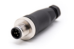
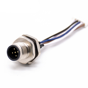
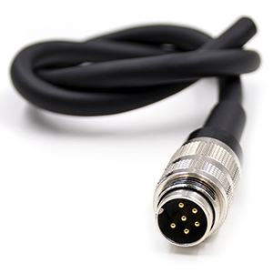
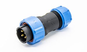
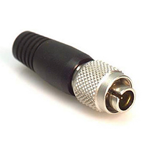
M Series Connectors
Are lightweight triplestart ratchet coupling type connectors designed for avionics, aerospace, Harsh Environment Connectors, security, motorsport and heavy duty applications.
M23 connector often applies to industrial automation, transportation, electric power, medical products, and other fields. The function is mainly based on signal transmission and power connection.
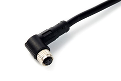
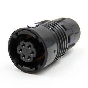
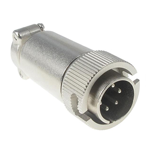
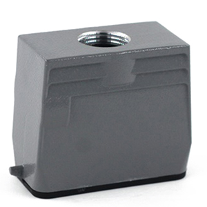
These connectors also have a smooth external body design that prevents dust and contaminants from falling in, thus aiding in industrial processes.
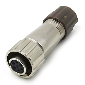
Designed to perform under harsh environmental conditions with rugged chassis, high-reliability contact technology, and simple assembly procedures, these connectors can maintain good performance.
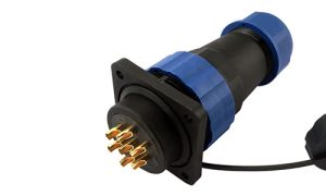
Custom solutions and platform products are available in modular or round bodies designed to ensure a perfect fit in industrial environments where connectors are necessary to operate, control, power, or monitor equipment.
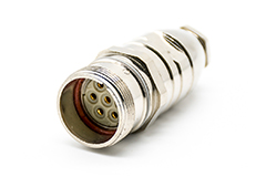
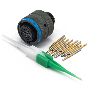
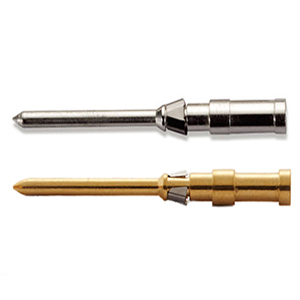
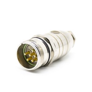
The connector contact parts are gold plated and have half the impedance of conventional contact designs. It is unaffected by vibration, has extremely low insertion/extraction forces, and offers 360-degree contact effectiveness. This advanced technology is used in all-around contact device solutions.
It is superior to other connection methods in terms of reliability of performance, number of contact cycles, contact strength, contact impedance, and values. We provide users with the most stringent requirements for connections in various complex environments such as high speed and high vibration.
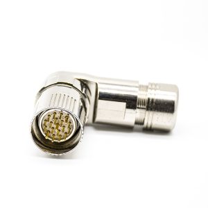
| Direction | Straight/Angled |
|---|---|
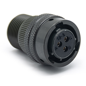
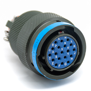
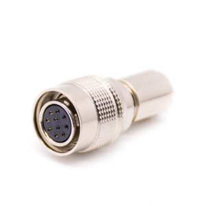
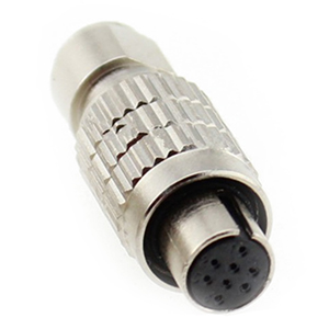
| Pin Configurations | 6、7、9、12、16、17、19 Pins |
| Shell Material | Copper Alloy |
| Shell Plating | Zinc Plating |
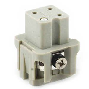
| Insulation Material | PA66 |
| Contact Material | Copper Alloy |
| Contact Plating | Gold Plating |
| Rated Voltage | 250V for 6/7/9 pin,150V for 12/16/17/19 pin |
| Rated Current | 20A for 6/7 pin, 8A for 9/12/16/17/19 pin |
| Insulation Resistance | ≥1000 MΩ |
| Contact Resistance | <3 MΩ |
| Coupling Method | Threaded Connection |
| Temperature Range | -40°C〜+ 125°C |
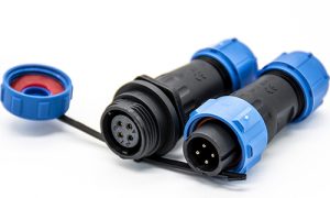
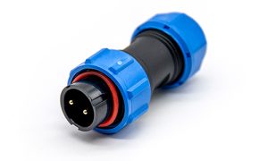
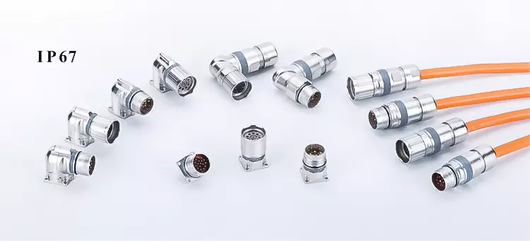
| Protection Degree | IP67/IP68 |
| Mechanical Operation | >500 mating cycles |
| Wire Gauge | 2.5mm²/(14AWG) for 6/7 pin, 1.5/2.5mm²/(16/14AWG) for 9 pin, 1.0mm²/(18AWG) for 12/16/17 pin, 1.0/1.5mm²/(18/16AWG) for 19 pin |
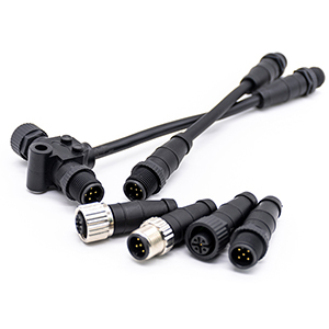
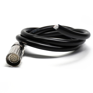
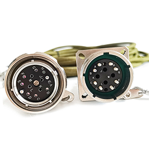
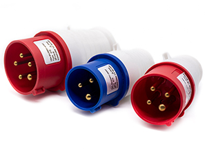
Among them, M23 connectors are used for servo motor connection applications. It is a more universal standard connection device than a junction box; it is by far the most commonly used motor connection system.
A servo motor is an engine that controls the operation of mechanical components in a servo system. It is an auxiliary motor indirect variable speed device.
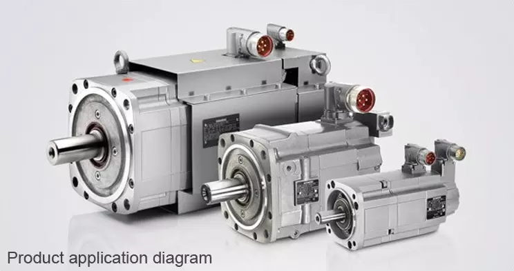
In an automation control system, the servo motor is the actuating element. It can convert the received electrical signal into torque and speed on the motor shaft; to drive the movement of the control object; can control the speed; the position accuracy is very accurate; it is widely used in the automation equipment of many industries.
Dust rating (first number):6 Prevents penetration of fine dust (dustproof), completely dustproof.
Waterproof rating (second number):6 Protection against fluid flushing or powerful spraying of liquid.
In the case of powerful injection of fluid or fluid flushing, the fluid cannot penetrate into the equipment and affect the regular operation of the equipment.
7: Equipment in working condition is immersed in a certain pressure of the liquid after a certain period of time. The liquid can not penetrate into the equipment inside the regular operation of the equipment.
8: The product is suitable for permanent immersion in liquid (on this occasion, different product manufacturers need to provide a detailed definition); this level of protection usually requires gas tightness.
However, depending on the transmitted signal, there are cases where the liquid can also have penetrated the product or equipment. But it is essential to ensure that there is no impact on the normal operation of the product or equipment.
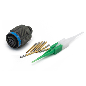
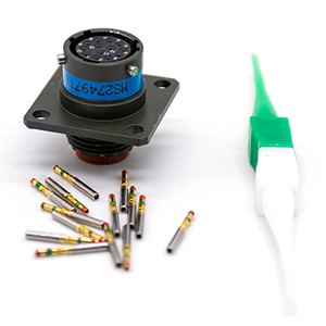
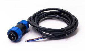
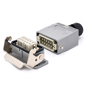
The connectors are crimped to achieve good mechanical properties, electrical properties, and airtight connections. This connection ensures the long-term stability of the connection and is therefore very reliable.
Manually operated crimping tools are available for crimping operations on crimped connectors. Please note the following points when performing the crimping operation to match to achieve the desired crimping effect.
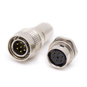
There are two types of crimp connectors from the manufacturing process: turned parts and stamped parts. These two types of connectors have different characteristics depending on the manufacturing process of the connected wire parts.
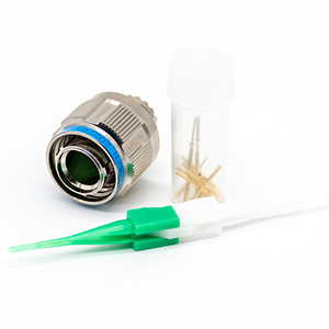
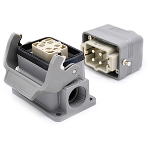
Turned connectors: This type of connector is widely used. With this connector, it is important to pay attention to the size of the connector, which must be compatible with the cable we are crimping. Be sure to use a crimping tool or die to crimp and adjust to the correct position.
Pressed connectors: The crimp groove of this connector can crimp a wider range of wires and ensure reliable crimp quality. In addition, this stamping connector in the jack and the plug will usually be a less plugging force due to the jack and the pin contact area being larger and the material used in this connector being more flexible. Pressed connectors are available in rolls for crimping operations using automatic crimping machines.
Connector: A connector is a general device used to provide an electrical connection at the interface of two conductors.
Plugging cycle: Plugging cycle refers to the maximum number of times a connector can be used to plug and unplug; beyond this maximum number of times, the connector will fail in electrical or mechanical performance.
The upper-temperature limit: The upper-temperature limit is the maximum temperature environment for the normal operation of the connector. It is the full value of the connector temperature rise due to the connector conductivity or other external causes.