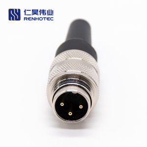
M Series Connectors
Are lightweight triplestart ratchet coupling type connectors designed for avionics, aerospace, Harsh Environment Connectors, security, motorsport and heavy duty applications.
Circular connectors like M8, M12, and M16 are critical components in industrial automation, providing robust and reliable connections for sensors, actuators, and communication devices. Their key advantage lies in simplifying installation and maintenance, allowing for quick replacement of field devices without extensive rewiring, which significantly reduces machine downtime and improves operational efficiency in demanding factory environments.
The International Electrotechnical Commission (IEC) standardizes these connectors under the IEC 61076 series. These standards meticulously define mechanical dimensions, electrical characteristics, pin assignments, and anti-mismating coding to ensure interoperability and safety across manufacturers, providing a universal framework that guarantees consistent performance and reliability in global industrial applications.
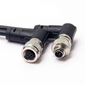
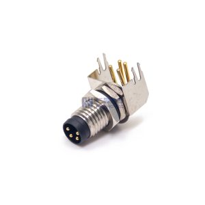
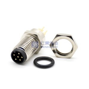
The M8 connector standard defines primarily two coding types: A-code and B-code. A-code 3-pin and 4-pin versions are the most common, both rated for 4A current, while the less common B-code 5-pin variant is often used for specific fieldbus signals, with all types featuring a distinct keying mechanism to prevent mis-mating.
M8 A Code
M8 B Code
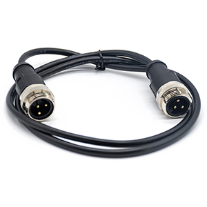
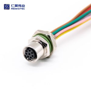
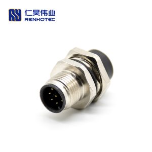
The M12 connector, identifiable by its M12x1 thread, is arguably the most ubiquitous circular connector in industrial environments. Its versatility stems from multiple “coding” types, each designed for specific signal, power, or data purposes, preventing accidental misconnection and ensuring system integrity across a vast range of automation components.
A-coding is the standard for DC sensors and general I/O interfaces. It is available in pin configurations ranging from 2 to 17, with voltage and current ratings decreasing as the pin count increases due to reduced electrical clearance, making the common 3-pin and 4-pin versions suitable for higher power, while higher-density versions are reserved for low-power signals.
As you can see above, the 101 detailed specification specifies five coding methods for M12 circular connectors. A, C code has a variety of types. The higher the number of pins, the smaller the rated voltage and rated current, according to its characteristics, can be suitable for different applications.
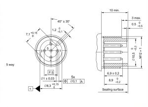 M 12 A Code 5 Way Type Size Chart
The above diagram is the dimensional drawing of the A-code 5-way type. This coding method is the most commonly used one; basically, most proximity switches are used this way. Only some 3-pin or 4-pin ones are in which individual pins are not in use.
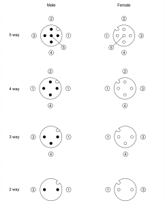
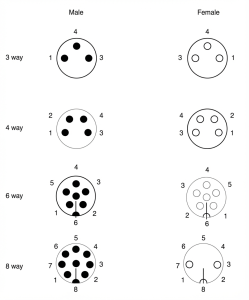
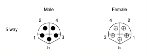
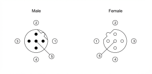
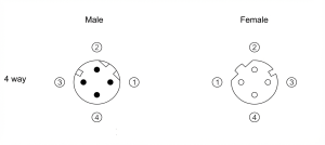
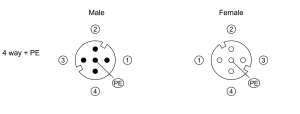
M12 A Code 5 Way
The diagram above shows the pin out of the A-code 5-way type, from 2-way to 5-way, and they are compatible in size. That is, if there is a 2-pin male header, it can be inserted into any of the female headers of that type.Most manufacturers make female headers of the 5-hole type for the convenience of mold opening. Only the number of lead wires is different.
As you can see from the red circle shown in the figure, there is a small gap between the 1,2 pins of the female head. The corresponding position of the male head is a bump, designed to prevent misplacement and ensure that only the same code and the same number of plugs can be inserted correctly.
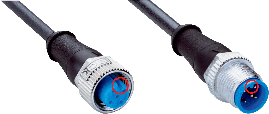
M12 Connector Keying and Polarization
A code 5-way type using the pin thickness of 1mm, rated current 4A. 2,3,4 way pin distance to ensure the rated voltage to 250V, 5-way pin due to the 5th pin is located in the middle resulting in pin distance shortened, electrical insulation distance reduced, so the rated voltage of 60V. If you use the 5-way pin structure, please note that the use of occasions does not exceed 60V.
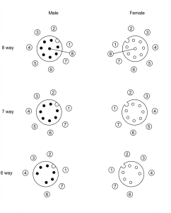
M12 A Code 8 Way
Several M12 A-code 8-way type pin types are also compatible, with a pin diameter of 0.8mm, a rated voltage of 30V, and a rated current of 2A.
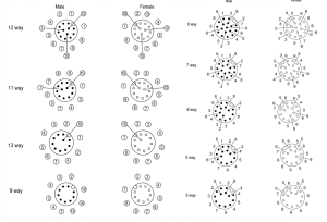
M12 A Code 12 Way and M12 A Code 17 Way
The M12 A-code 12-way and 17-way types are also compatible, using a pin diameter of 0.6mm, a rated voltage of 30V, and a rated current of 1.5A.
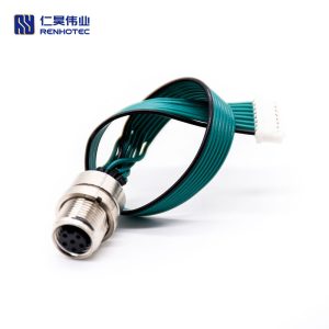
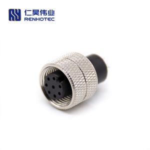
B-coding is commonly used for fieldbus systems like Profibus. It shares a similar pin size with the A-code but features a different keying position, making it physically incompatible and ensuring dedicated use in networks requiring a specific 5-pin configuration for data and power.

M12 B Code
M12 B code pin size 1mm, rated voltage 60V, rated current 4A. The pin distribution is no different from the A code, but their anti-mistake (anti-dull) structure is different and can not be inserted incorrectly.
M12 C Code
M12 C code several sizes are incompatible, 3,4-way pin diameter 1mm, rated voltage 250V, rated current 4A. 5-way pin diameter 0.76mm, rated voltage 60V, rated current 2A. 6-way pin diameter 0.76mm, rated voltage 30V, rated current 2A.
M12 D Code
M12 D-code pin diameter 1mm, rated voltage 250V, rated current 4A. It is worth mentioning here that D-code and A-code 4-way have the same size but do not interpolate due to the different anti-error insertion mechanisms, ensuring reliability. Care needs to be taken when selecting the type.The D-code specification specifies that a data rate of 100MHz can be achieved, so this coding method was also used for Fieldbus in the early days.
M12 P Code
M12 P-code pin diameter 1mm, rated voltage 60V, rated current 4A. P-code and A-code 5-way have the same size but are not inter-inserted due to the different anti-mis-insertion mechanisms, ensuring reliability.
There are also X-coded M12 circular connectors today, mainly for high-speed Ethernet transmission. One hundred nine specifications use type X and type H, type X, and H no longer use X coding and H coding, but most manufacturers still use X coding and X coding to describe to unify.
The rated voltage of the two connectors: 50V AC/60V DC, rated current: 0.5A, the number of pins is 8 pins 4 pairs.
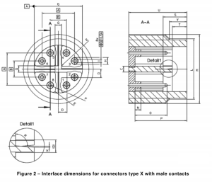
Type X Pinouts and Dimensions
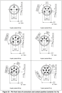
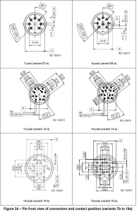
Type H Pinouts and Dimensions
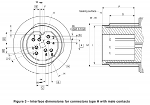 Type H Pinouts and Dimensions
Interface Dimensions for Connectors Type H with Male Contacts
Recommended TIA568B wiring method.
The M16 connector offers a larger form factor than the M12, accommodating more contacts or handling higher power levels. It is used in applications where more signals or higher current capacity are needed than an M12 can provide, such as in complex sensors, small motor drives, or as a robust interface in high-vibration environments.
M16 Connector Rating Parameters
Rated voltage – Impulse voltage – Pollution degree
Find Your Robust Connection Solution
Selecting the right industrial connector is critical for system reliability and performance. Whether you need a compact M8 for space-constrained sensors, a versatile M12 for data, signal, or power, or a robust M16 for higher current and complex wiring, our engineering team is here to ensure you get the perfect match for your application.
Contact our experts at [email protected] to discuss your M8, M12, and M16 connector requirements, request custom solutions, and view our full product catalog!

As an industry specialist at Renhotec Group, I have years of expertise in the field of electronic interconnection. Founded in 2008, Renhotec Group is a global leader in designing and manufacturing connectors, cables, and custom electronic components for a wide range of industries. We are committed to providing high-performance interconnect solutions, leveraging technical innovation and rigorous quality standards to empower global customers across industrial, RF, and EV sectors.