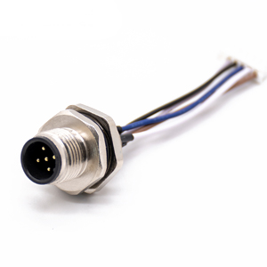
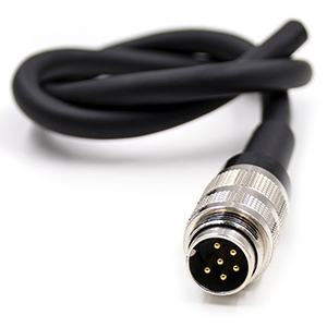
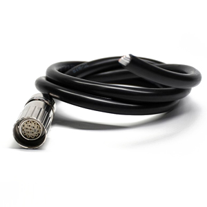
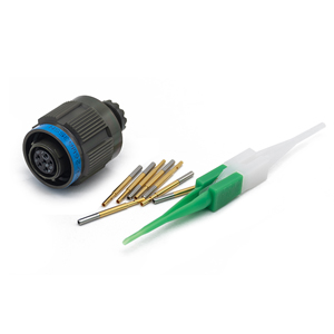
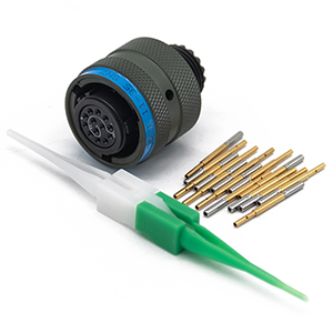
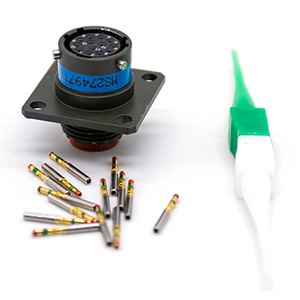
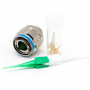
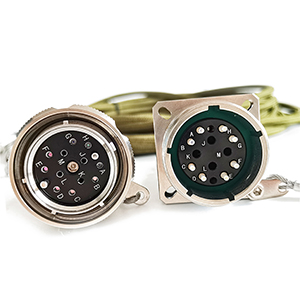
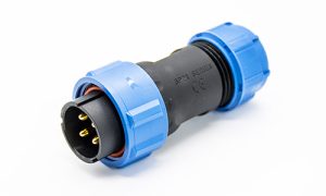
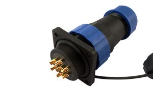
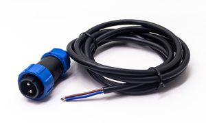
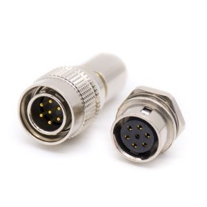
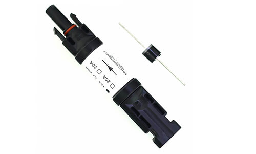
M Series Connectors
Are lightweight triplestart ratchet coupling type connectors designed for avionics, aerospace, Harsh Environment Connectors, security, motorsport and heavy duty applications.
Click to see what should be paid attention to in the design and selection of high-voltage connectors (top)
2. Connector temperature resistance and power consumption
If the connector (mainly the contact part) exceeds the specified operating temperature limit, the connector will reduce its safety characteristics due to heat, or even fail and be damaged. The main reasons for the increase in temperature of the connector are as follows:
1) Environmental factors, the layout position is easily affected by high temperature or is in a sealed cabin where heat is concentrated. If the layout position cannot be avoided, the temperature resistance of the connector should also be considered when selecting (such as Table 1).
| standard | Maximum operating temperature range | Class level |
| Technical requirements for high-voltage and high-current wiring harnesses and connectors for electric vehicles | -40℃~125℃ | T3 |
| SAE_USCAR_37 | -40℃~175℃ | T5 |
| LV215 | -40℃~150℃ | / |
Table 1 Connector operating temperature range
2) The connector heats itself, and the main influencing factors are heat dissipation of the contact resistance of the mating contact or poor crimping.
An important measure of the electrical performance of a connector is the contact resistance between the connectors. The smaller the contact resistance, the smaller the voltage drop, which means the lower the electrical loss, and the lower the temperature rise, and the higher the connection terminal Service life.
After the contact is heated, the plating layer will be affected, or an insulating film layer will be formed in the contact area, which will increase the contact resistance, further aggravate the temperature rise, and form a vicious circle.
If the connector is heated beyond the limit, the wiring harness will be burnt when the thermal failure is serious, and the insulating material will be chemically decomposed, which will reduce the insulation performance. In severe cases, the positive and negative poles of the connector may break down and short-circuit after the insulation material is thermally melted.
According to the Volkswagen VW80834 standard, the contact resistance of the connector cannot exceed the limit in Table2:
| Cable cross-sectional area mm² | Crimping resistance | Contact resistance (total resistance, including crimp resistance) | ||
| Unused mΩ | After aging mΩ | Unused mΩ | After aging mΩ | |
| 2.5 | 0.17 | 0.35 | 1.17 | 2.34 |
| 4.0 | 0.11 | 0.22 | 0.72 | 1.44 |
| 6.0 | 0.09 | 0.18 | 0.68 | 1.36 |
| 16 | 0.05 | 0.1 | 0.43 | 0.86 |
| 25 | 0.035 | 0.07 | 0.40 | 0.80 |
| 35 | 0.029 | 0.059 | 0.39 | 0.78 |
| 50 | 0.025 | 0.05 | 0.36 | 0.72 |
Table 2 Connector contact resistance range
After the connector cable is crimped completely, the contact resistance calculation formula is as follows:
Rtotal=Rcrimp1+Rcontact+Rcrimp2
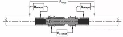
Figure 1 Schematic diagram of connector contact resistance
a) Generally speaking, the crimping of the wiring harness is outsourced to the optional connector manufacturer, which can better guarantee the crimping reliability of the connector. In practical applications, the thermal failure of the connector is mostly due to poor crimping of the wire harness, such as insufficient crimping ratio, resulting in flash crimping, or excessive crimping ratio, resulting in incomplete crimping.
| Cable cross-sectional area mm² | Pulling force N |
| 2.5 | 200 |
| 4.0 | 310 |
| 6.0 | 450 |
| 16 | 1500 |
| 25 | 1900 |
| 35 | 2300 |
| 50 | 2800 |
| 70 | 3400 |
| 95 | 4200 |
Table3 Crimp pull force strength requirements
b) The interface structure of the connector, such as the material/plating type and its purity, thickness, geometry, etc. determine the performance of the connector, including contact resistance, insertion force and insertion life.
The structure of the high-voltage connector terminal contact piece mainly includes split type, crown spring type, torsion spring type, strap type, etc. Different structural forms determine the electrical contact mode (surface contact, line contact and multi-point contact). ), which form to choose depends on the application of the connector. For frequently pluggable connectors, according to the principle of parallel shunting, the number of current-carrying bridges is used to achieve the purpose of reducing contact resistance.
Connector plating generally chooses silver with low contact resistance (as shown in Table 4). The thickness of the plating of different manufacturers’ products is different (the coating is too thin and wears badly, and the adhesion of too thick coating is insufficient). The selection should be based on different applicable occasions. Such as indoor/outdoor, frequent plugging and unplugging, etc.
For example, for charging connectors, the laboratory plug-in test can meet the goal of 10,000 times stipulated by the national standard. However, under the actual conditions of outdoor use, the first environmental conditions faced are worse than those of the laboratory (such as humidity, heat, dust, etc.); secondly, personnel operation Whether the specification is subject to random uncertainty. If used or maintained improperly, the local plating of the charging connector will be severely worn and “copper leakage” will occur, and copper rust will occur during use, resulting in a reduction in the effective current-carrying surface/point.
| material | Conductivity m/Ωmm² | Resistivity Ωmm²/m |
| copper | 57 | 0.017 |
| tin | 9 | 0.110 |
| silver | 62 | 0.016 |
| gold | 41 | 0.024 |
| nickel | 14 | 0.07 |
Table 4 Conductive properties of metal materials
In addition, in the application of connector selection, attention should be paid to the structure of the connector terminal. If the plug-in terminal is connected at a 90° right angle, the screw connection structure should be avoided. With this structure, the thread tooth pattern matching accuracy is very tight, but in the process of thread processing and wire harness assembly, incomplete connection and contact cannot be avoided. Especially for high-current terminal connections, in long-term use, the terminal thread teeth will be locally overheated, and the connector faces the risk of thermal failure.
Regarding this point, you can also refer to the VW80304-2013 standard formulated by Volkswagen, which stipulates that the cable outlet is 180°, 90°, and the right-angle 90° method does not allow threaded connection.
3. Connector life and cost
For connector performance and life requirements, the Volkswagen standard stipulates: Passenger car development projects must guarantee a full-featured life cycle: at least 15 years or 300,000Km (≥8000h action+30000h charging), and commercial vehicles must guarantee at least 15 years or 1000000Km.
In the connector selection process, product cost should not be the first consideration. Only on the basis of meeting performance requirements can it be possible to reduce costs and increase efficiency, unless it is willing to sacrifice the reliability of the vehicle’s high-voltage electrical connection.
Of course, in order to ensure product performance, excessive selection of structure and specifications should also be avoided in the selection, which will increase the cost of the product.
To sum up:
High-voltage electrical connection systems involve electrical architecture and safety, and connector products are related to the development of the entire industrial chain.
The performance of the product is determined by the structure and material of the product. After the product structure is optimized to the extreme, the competition of product performance is the competition between basic materials and physical research.
In product selection and application, if you do not grasp the interface material of the connector and understand the failure mechanism of the connector, it is impossible to scientifically evaluate the reliability of the connector.