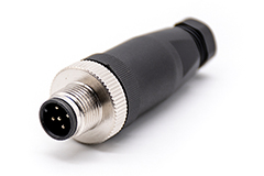
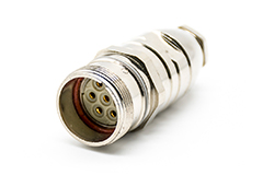
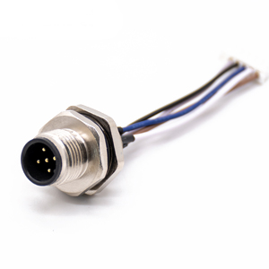
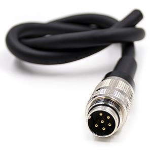
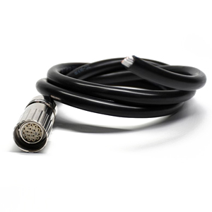
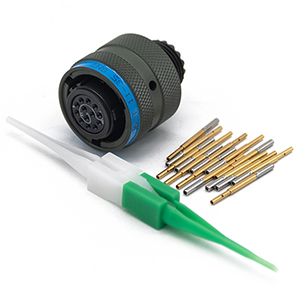
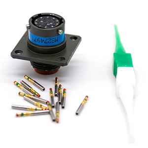
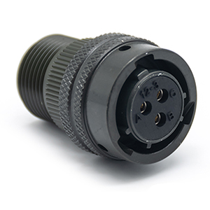
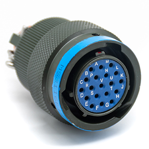
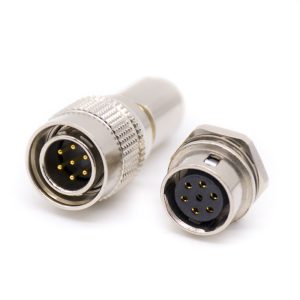
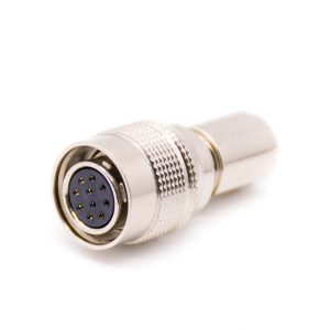
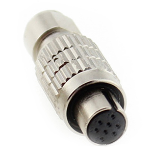
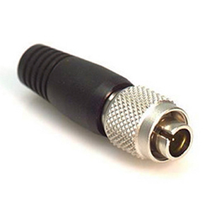
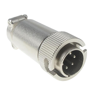
M Series Connectors
Are lightweight triplestart ratchet coupling type connectors designed for avionics, aerospace, Harsh Environment Connectors, security, motorsport and heavy duty applications.
The concept of a high-voltage interlock is introduced in the connection design for the entire high-voltage interconnection system. To ensure the safety of the high voltage system. The high-voltage circuit is first contacted and energized when the connector is inserted. Then the high-voltage interlock signal circuit is energized. The high voltage interlock signal is first disconnected when disconnected. Then the high voltage circuit is disconnected.
Most connector manufacturers place the high voltage interlock design inside the connector. Other manufacturers place the high voltage interlock outside the mating cavity through a secondary construction design.
It is critical to ensure the stability of the high voltage interlock circuit. The possible effects will be terrible if the high-voltage interlock is not continuous. For example, an abnormal signal from the high-voltage interlock circuit while the car is in motion could cause the entire car to suddenly lose power and fail to operate properly, causing a traffic accident.
It is important to understand that a true secondary lock does not have the function of secondary protection but rather protects it more effectively. It means that the secondary lock is essential to ensure that the first lock is protected after the primary lock if it fails or does not operate to verify that it is in place.
The moment arm mechanism is the most common mechanism used in secondary lock construction in combination with the primary lock. As the primary lock is related to the insertion and removal force, a form similar to the moment arm mechanism is required according to the mechanical design concept, which achieves labor savings and allows the connector to be easily inserted into place.
USCAR talks about the ergonomic operability of many force arms for the force arm requirements. USCAR also specifies the force requirements for the relevant master and secondary locks in the case of mating and non-mating. Most of us would think of USCAR as the standard for connectors, but I think the USCAR standard is more than just a technical standard. It also guides designers in the design process on how to make the structure reliable and how to make the structure and performance reliable given the structure and performance. It also provides a better product experience for the customer.
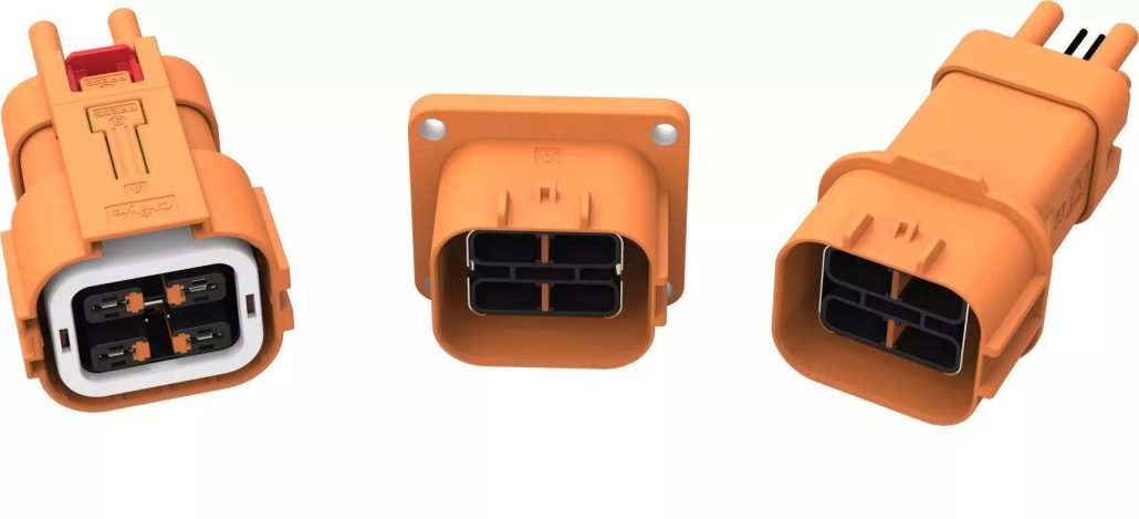
There are three main arrangements for the protection of connectors.
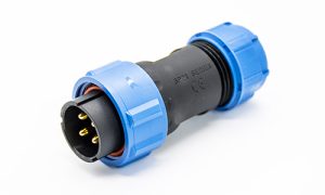
As the market for electric vehicle high-voltage connectors grows, so do the performance requirements of OEMs for product protection. In the early stage of industry development, IP67 protection requirements have been able to meet the requirements of most customers.
However, at a later stage, as the connector product protection failures appear in the market, there are more and more cases of product leakage, insulation failure, and even ablation.
The gradual improvement of protection requirements has become the development trend of electric vehicles. The current IP67 requirements can not meet the normal use of the requirements. Of course, this is not absolute, depending on the location of the connector on the vehicle.
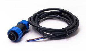
According to the layout of the entire vehicle’s high-voltage circuit, it will be suspended under the vehicle chassis. It is a principle that high-voltage electricity cannot enter the cabin. Therefore, most high voltage connectors are located near the ground or the wheels on the chassis. When the weather is terrible, such as bad weather, heavy rain, or severe cold weather, the water carried by the tires can affect these connectors.
If you are familiar with this test, domestic standards do not have IP6K9K. If you use IP67, the impact pressure of the high-pressure water gun is not as great as 6K9K.
When a car suddenly wades through water at high speed, the water pressure rushing to the connector instantly can be very high. So sometimes, it is not easy to meet the actual use of IP67 requirements.
In this regard, the current domestic standard QC/T1067 and foreign standards USCAR will be the connector seals into the S1 and S2 levels. For class S2, the application is specified for the lower chassis position, and 6K and 9K are recommended. Therefore, if future protection connections are made, 6K and 9K must be used. If the connector is not in the above position, the design of IP67 can meet the requirements of the whole vehicle.
Electric vehicles have a lot of electronic devices. The current will generate magnetic fields. The whole vehicle components should have the ability to resist interference. Especially now, the electric vehicle is a carrier, and driverless will have more development, so this technical issue is significant. Shielded connectors and cables are essential for high-voltage systems, but we must prioritize system-level layout.
If your OBC, the location of your layout, including the system DCDC itself, may have some innate problems, no matter how good the connectors are, there will be all kinds of signal interference problems. So we must first consider the system type and then the component level.
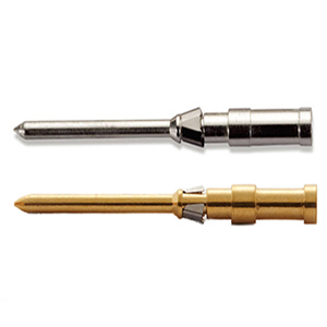
OEMs are also considering this method. We call it a spring contact (in English), which is a spring connection. This structure also has many benefits, as the volume and space will be smaller and have more contact points. There are many manufacturers of this structure, mainly represented by companies such as BMW Spring in Switzerland and Basel in the United States. They have many practical and proven application cases in this field.
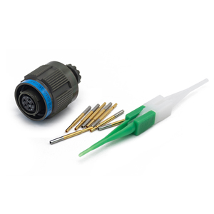
In most cases, the connection between the wire and the shield will be in the form of a metal inner, and outer ring crimped together. The shield is placed between the two metal rings, and the shield and metal ring are deformed by cold pressing. Tightly fixed. In addition, we have a shielding method that uses a structure similar to a strap spring instead of a spring connection. You can see this structure in technically mature Harsh Environment Connectors products. The structure applies to the shielding layer of new energy electric vehicles, which can meet the performance requirements and is a stamping part, suitable for mass production and cost-effective.
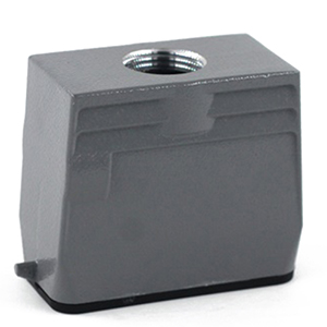
The material of the connector insulation is generally PA66, PBT, ABS, PC, etc. Contact materials are generally brass, phosphor bronze, beryllium copper, etc. But copper-nickel silicon material is the majority of foreign appearances. Connector shell materials are generally plastic and metal.
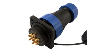
Due to the demand for lightweight vehicles, especially passenger car manufacturers, under the premise of meeting product performance, they will try their best to choose plastic connectors to control the vehicle’s weight.
Because the mechanical strength of metal materials is better than plastic. Therefore, in some harsh environments, metal connectors are more suitable. For example, special vehicles, muck trucks, and electrical connection parts are not protected during the layout of the entire vehicle. Metal connectors are slightly better than plastic connectors in terms of environmental impact and mechanical strength.
Regarding the shielded connector, since the metal connector shell is used for conducting the shielding, it forms a carrier for shielding protection. Under normal circumstances, metal connectors are easier to achieve better shielding effectiveness than plastic connectors, and the appearance structure is more compact.