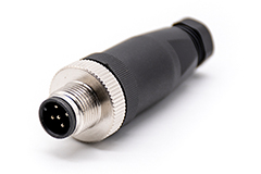
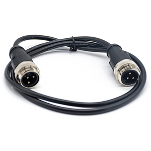
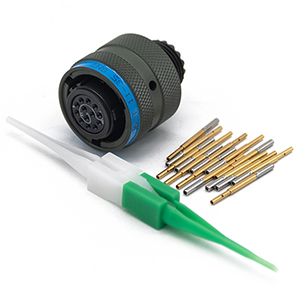
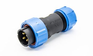
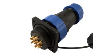
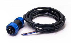
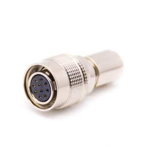
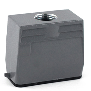
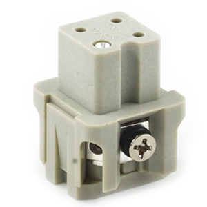
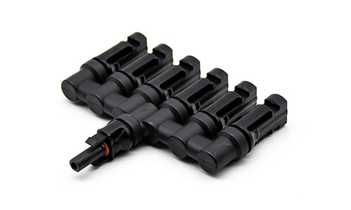
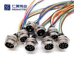
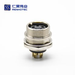
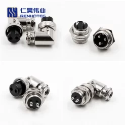
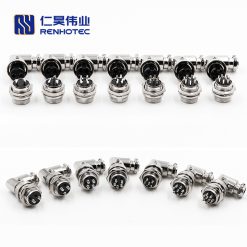
M Series Connectors
Are lightweight triplestart ratchet coupling type connectors designed for avionics, aerospace, Harsh Environment Connectors, security, motorsport and heavy duty applications.
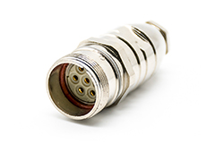
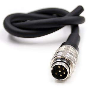
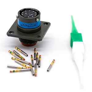
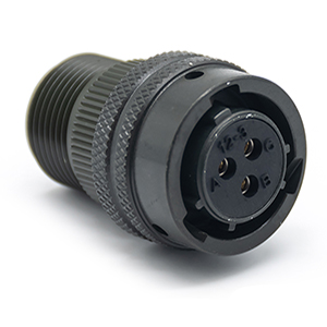
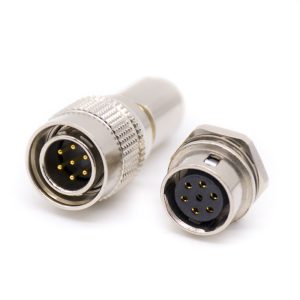
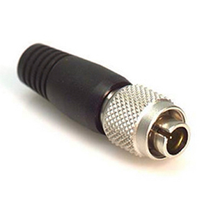
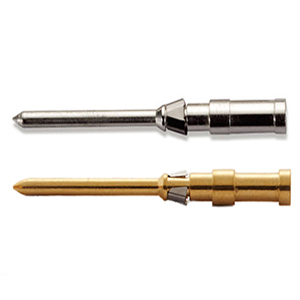
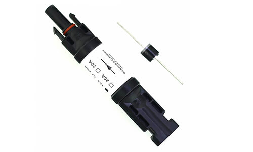
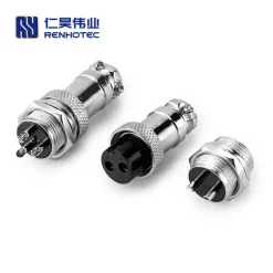
GX16 aviation connector is often used for applications such as CNC conversions. Usually soldered connectors usually have good spacing and clearance, and even heat shrink tubing can be used to protect the pins, so crimp connectors are preferred. Connectors that meet MIL specifications are also preferred, and they are usually nicer.
As far as appearance goes, the GX16 connector seems to look pretty good. However, the internal space is relatively small and can be a bit tight for soldering. The lack of available space (length) requires more effort.
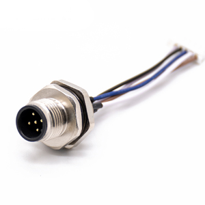
Each stepper requires two cables, a four-conductor cable for the stepper drive and a six-conductor/shielded cable for the integrated encoder. The four-conductor cable is relatively simple, except for the shorter length. Now, let me share what I did for the 6/shielded cable set.
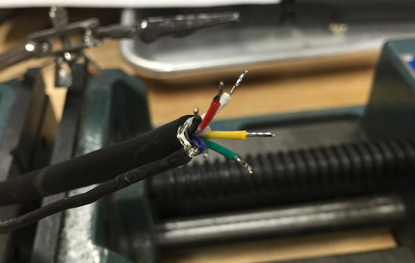
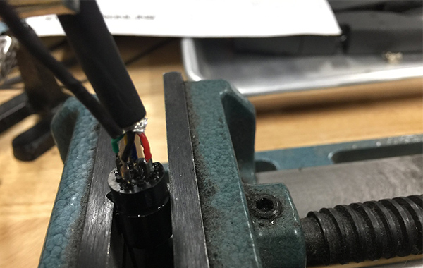
Strip off the outer insulation and arrange the cables to match the pin arrangement. With limited space available, it is critical to ensure that each cable is properly connected to the pins.
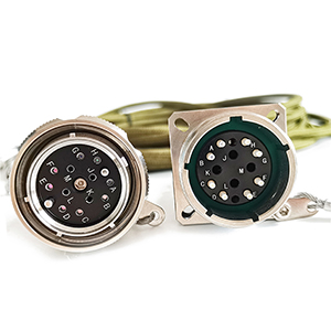
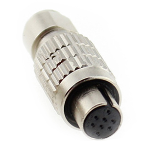
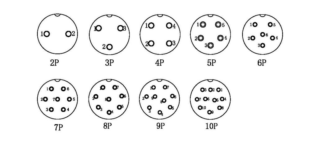
GX16 Wiring Diagram-Male Socket
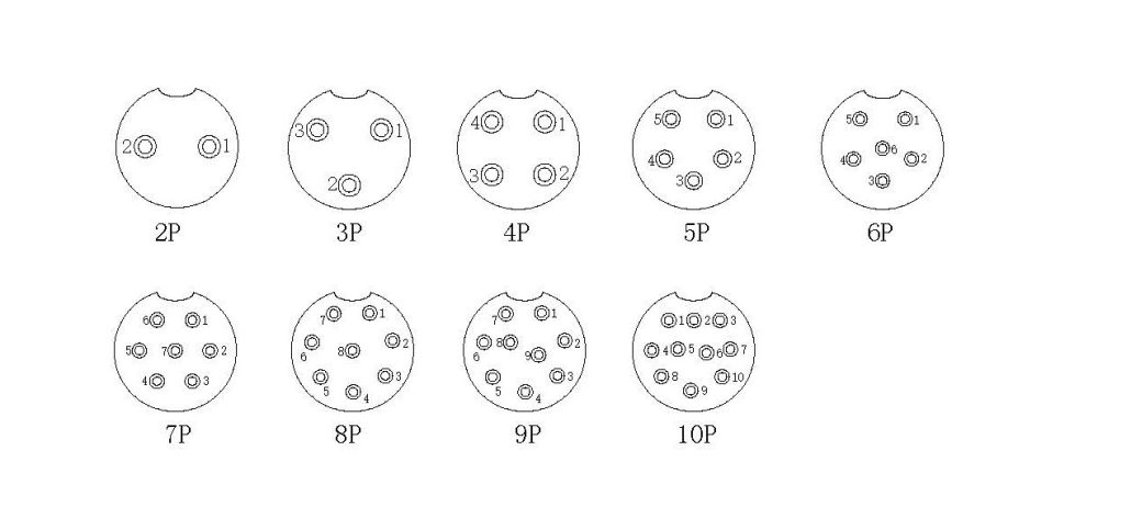
GX16 Wiring Diagram-Female Plug
Strip about 1/8 inch of insulation off the end of each cable and apply a small amount of water-soluble flux to the cable. If the insulation is of poor quality, apply gentle heat to melt it during soldering to ensure a strong connection to the pins.
Tin each cable individually. This minimizes spattering and gives a nice tinned finish.
These steps help ensure a quality and reliable cable connection.
Please note that using heat shrink tubing to wrap the shield will make future maintenance much easier. There is no doubt that there is nothing worse than the frequent manipulation of tiny shield cables, which are always prone to misplacement.
When tinning connector pins, be careful not to under- or over-tin them. Simply fill the tin cups without overdoing it. Again, just add a drop of flux and it will all become much easier and faster.
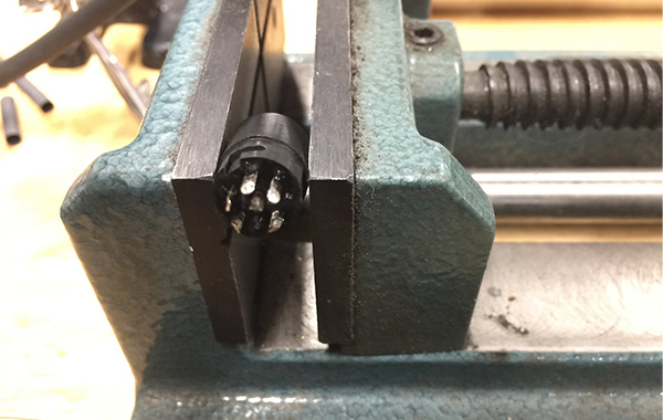
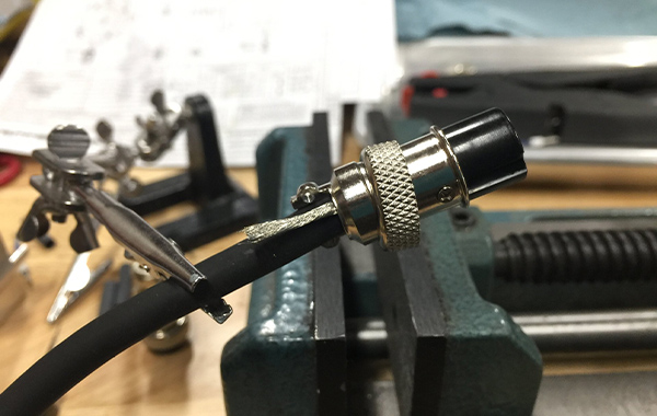
Use the vise with care. Using too much force may damage the connector, so be gentle enough only to prevent the connector from moving. A small Wilton vise is preferred because it is medium height and heavy enough to stabilize the connector and not easily make it move.
The cables and pins are now tinned. It’s time for the critical step, dealing with the internal pins first. Once the external pins have been completed, it will be more difficult to access the internals again. Remember again to add a drop of flux to the cables and pins and be sure to keep the soldering iron tip clean to avoid overheating and scorching.
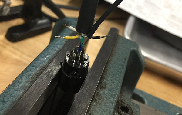
The blue cable connects to pin 6 in the center. Make sure the clip holds the cable vertically to ensure that the cable stays in the correct position and does not wiggle. Select a direction and proceed to install the external pins. The green cable is next and connects to pin 5.
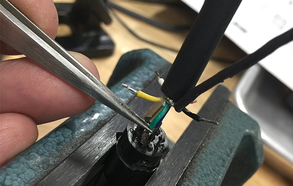
These are stainless steel fine tip tweezers. Solder will not stick to them and the fine tips conduct less heat. Grab the cable just below the insulation or you may damage the insulation during the soldering process. Simply touch the tip gently to the cable and when the solder melts, gently push the cable back into the cup. If you apply a “just right” amount of solder to both the cable and the cup during the tinning process, you won’t need to add more solder, it will flow naturally around the cable/cup.
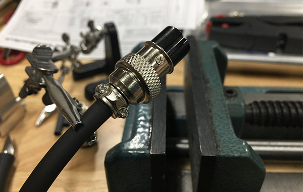
Handle each cable one at a time and realign the cable/connector to fit the next cable/pin. This completes all six cables.
Now, perform an inspection to ensure that all solder joints are intact and that no cables are exposed. Make sure the cables are the right length, just enough to cover the connector’s clip cover. Double check the color of the pin numbering, this is the last chance for easy access.
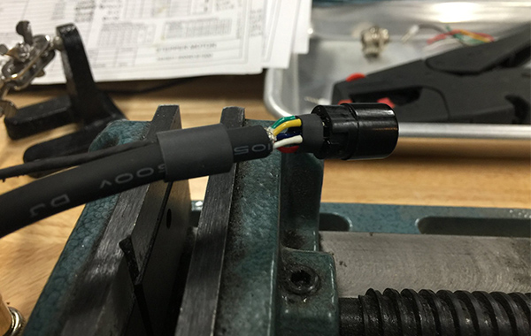
For these connections, the treatment is to place the GX16 connector clamp cover over the cables and use two pieces of heat shrink tubing with widths of 1/2 inch and 1/4 inch. Before soldering the cables/pins, be sure to double check the cable to make sure you haven’t missed any necessary elements.
Slide the 1/4-inch heat shrink tubing into place and heat it to shrink it.
This helps to hold the cables in place. Then slide the 1/2 inch cable in and shrink it. This way there is no chance of a broken cable shorting to the inside of the connector cover.
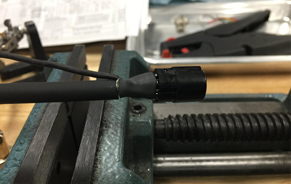
Next is the GX16 connector shell, slide it up to cover the shielded cable and tighten it.
Now remove the heat shrink tubing from the shielded cable.
Trim the shield cable to fit without sticking out, then tighten the clamp and place the shield cable on the cable between the screw holes.
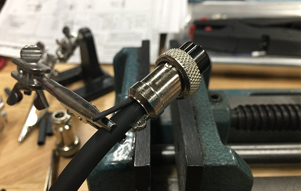
The final step is to tap the connection to check for conductivity and shorts between the ends/pins.

If you have any needs for our company’s products, please contact us by phone or email:
Mobil:(+86)18086610187
Email:[email protected]