Are lightweight triplestart ratchet coupling type connectors designed for avionics, aerospace, Harsh Environment
Connectors, security, motorsport and heavy duty applications.
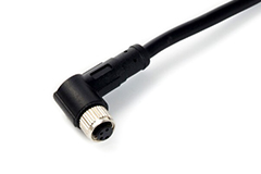
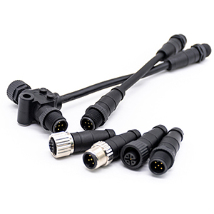
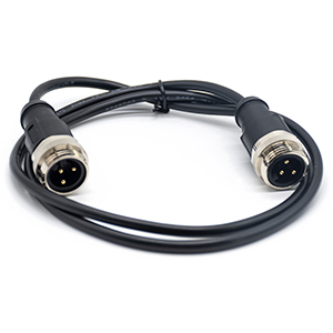
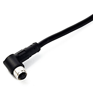
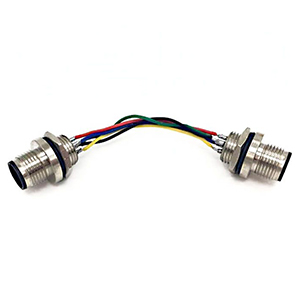
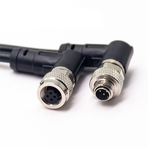
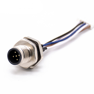
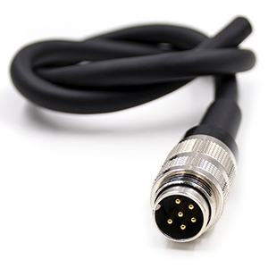
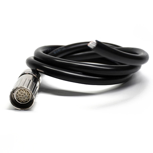
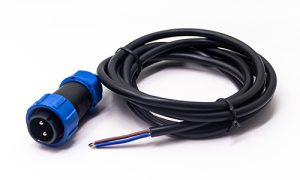
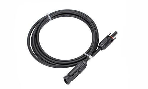
Circular Cable Assemblies
A circular cable assembly consists of a section of cable material with a circular connector at one or more
endpoints.
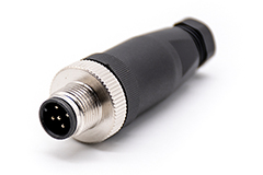
Renhotec offers a wide range of circular connector cable assemblies, especially M8, M12, and M16 cable assembly.
View all Circular Cable products >>
This series of connectors is an alternative solution to Lemo connector which are used in medical, industrial,
audio/visual, telecommunications, Harsh Environment Connectors, scientific research and measurement
applications.
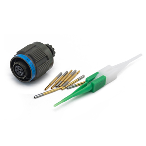
D38999s are popular and widely used subminiature circular connectors for Harsh Environment Connectors and
aerospace
applications. With three coupling methods, nine shell sizes, and a wide variety of contact arrangements, our
MIL-DTL-38999 connectors help give you the range of choices you need.
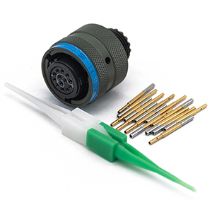
MIL-DTL-26482 connector, also known as the MIL-C-26482 connector. It boasts a wide array of pin configurations
and
can withstand high current loads. The series features heavy-duty connectors with solder contacts and bayonet or
“quick-disconnect” coupling.
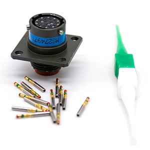
MIL-DTL-83723 Connectors also known as MIL-C-83723. This series features high-density circular connectors with threaded or bayonet coupling for aerospace.
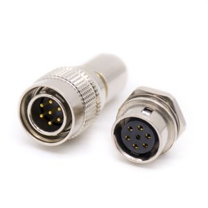
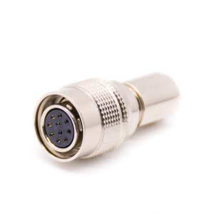
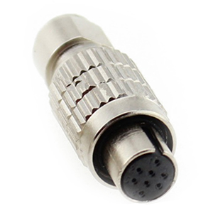
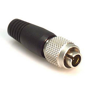
HR connectors are a lower-cost version, yet still provide a high "Value Add" while preserving the superior
characteristics of the HR connectors. Cable clamps are crimped using a special crimping tool, and the shells
have a
rubber boot which provides a flexible design that helps to prevent cable twisting.
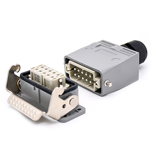
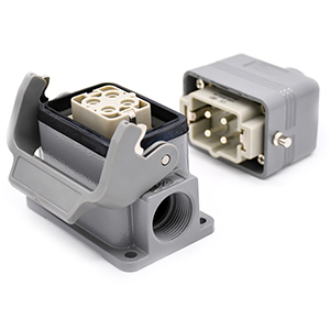
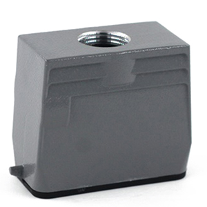
Heavy Duty Connectors (HDC) are robust industrial connectors for power, data, and signals in harsh environments.
They
offer reliability with aluminum or thermoplastic covers and IP65 to IP69k protection ratings, handling currents
from
10A to 80A and up to 216 contacts.
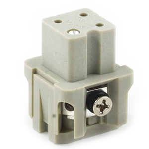
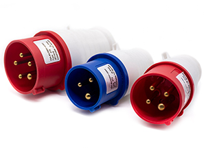
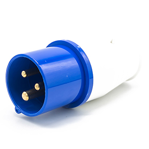
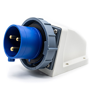
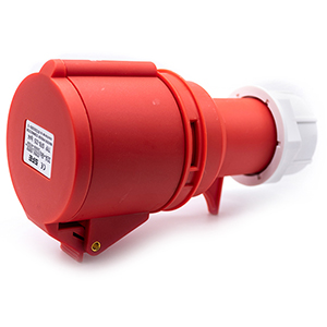
Renhotec provides a diverse range of durable industrial plugs, sockets, and related products designed to meet IEC
60309-1 standards for reliable connections in industrial and factory applications. Industrial plugs and sockets
have
3 Pin, 4 Pin and 5 Pin.
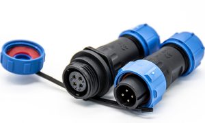
MS5015 Part Number Decoding & Assembly Guide for Engineers
The MS5015 series, also known as the MIL-DTL-5015(formerly MIL-C-5015) standard, represents one of the most versatile and widely utilized circular connector families in industrial and defense applications. Engineered for high reliability and the ability to withstand extreme environmental conditions, these connectors are the go-to solution for power and signal transmission in heavy machinery, factory automation, and servo motor systems. Whether you are a procurement manager sourcing alternatives for Amphenol or ITT Cannon, or a design engineer finalizing a BOM, understanding the granular details of the MS5015 specification is critical to ensuring system integrity.
Quick Decoding: How to Read the MS5015 (MIL-DTL-5015) Part Number?
Deciphering a military standard part number like MS3106A18-8PW can be daunting. Each alphanumeric character designates a specific mechanical or electrical attribute. Selecting the wrong prefix or class often leads to catastrophic failure in the field due to improper sealing or incompatible mounting.
The Anatomy of an MS5015 Part Number
To ensure 100% compatibility, the part number must be broken down into seven distinct sections:
Prefix (Military Standard):
MS31xx: Standard solder contact series.
MS41xx: Crimp contact series (ideal for high-vibration environments where field-repairability is not required).
N: Normal (Standard position, often omitted in part numbers).
W, X, Y, Z: Alternate rotations to prevent cross-mating of identical connectors.
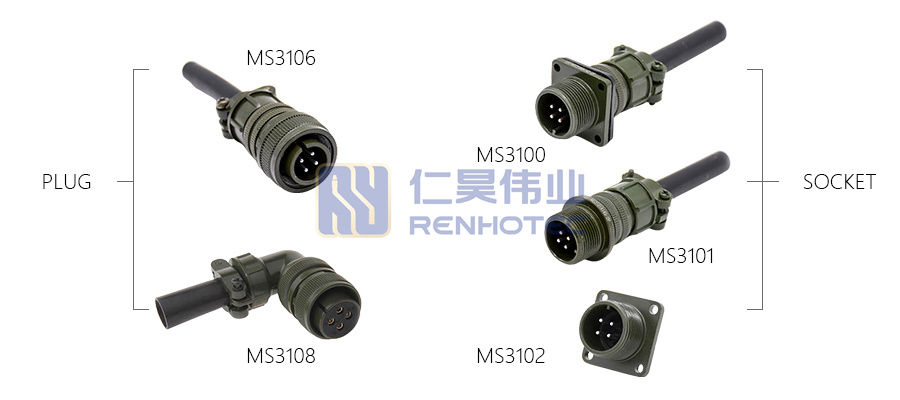
Decoding Shell Types: Understanding the Differences Between MS3100, MS3102, and MS3106
Selecting the correct shell type is primarily determined by your mounting environment and whether rear cable support (strain relief) is required. While they may share the same insert arrangement, their mechanical footprints differ significantly.
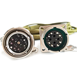
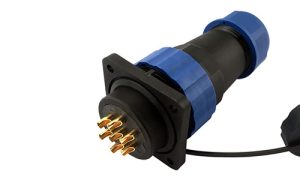
MS3100 (Wall Mounting Receptacle): This is designed for applications where the connector is mounted to a bulkhead or panel and requires a cable to be attached to the rear. It features rear threads to accommodate cable clamps (like the MS3057 series) and bushings.
MS3102 (Box Mounting Receptacle): Unlike the MS3100, the MS3102 is a “short” receptacle designed for compact box mounting where no rear cable support is needed. It lacks rear threads, making it ideal for internal chassis connections where space is at a premium.
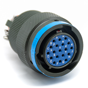
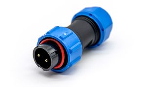
MS3106 (Straight Plug): This is the most common mating half for receptacles. It is a portable connector that attaches to the end of a cable. It always features rear threads for environmental sealing and strain relief accessories.
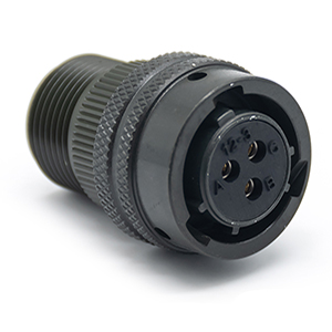
Selection Logic for 3-Pin and 4-Pin Connectors: Insert Arrangements vs. Service Ratings
In the MIL-DTL-5015 standard, the number of pins (contacts) is defined by the “Insert Arrangement” (e.g., 10SL-3 for 3 pins or 10SL-4 for 2 pins). However, the most critical factor for an engineer is the Service Rating, which determines the allowable operating voltage and the contact size.
Service Rating Impacts: A rating of “D” (Standard) vs. “A” (Heavy Duty) dictates the creepage and clearance distances between contacts. Choosing an arrangement with a Service Rating “A” allows for higher voltage applications compared to “Inst.” (Instrument) ratings.
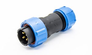
3-Pin & 4-Pin Examples: Common arrangements for a 3-pin Mil-spec connector include 10SL-3 (Size 16 contacts) and 14S-7 (Size 16). For 4-pin configurations, 10SL-4 or 14S-2 are industry standards.
Why Contact Size Matters: Larger contact sizes (e.g., Size 12 vs. Size 16) directly influence the current-carrying capacity. In servo motor applications, 4-pin connectors are often used for 3-phase power plus ground, where the ground pin might require a different service rating.
Technical Specifications: Material Science and Engineering Parameters
The durability of MS5015 connectors in “Harsh Environments” is a result of specific material choices mandated by the MIL-C-5015 specification. Below is a breakdown of the materials used in our high-performance alternatives.
Material and Process Breakdown
Component
Material Spec
Surface Treatment
Engineering Benefit
Shell (Housing)
High-strength Aluminum
Olive Drab Chromate
500+ hrs Salt Spray resistance; EMI shielding.
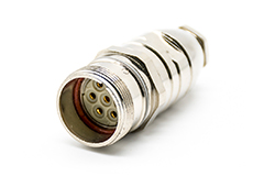
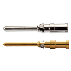
Contacts
Copper Alloy
Silver or Gold Plating
Optimized conductivity & anti-oxidation for low signals.
Insulator
Synthetic Rubber
Precision Molded
-55°C to +125°C range; high dielectric strength.
Sealing
Silicone Rubber
Compression Fit
IP67 Ready for Class E/F/R configurations.
Metal PlatingMetal ShellThreaded and bayonet
Step-by-Step Guide: MS5015 Assembly and Installation Process
Successful deployment of an MS5015 connector depends as much on the assembly quality as the component itself. For Class E, F, and R (environmental) connectors, improper sealing is the leading cause of field failures. Follow these engineering-standard steps for a reliable termination.
1. Wire Preparation and Stripping
Precision Cutting: Ensure the wire is cut square. Use a dedicated wire stripper to remove the insulation without nicking the conductor strands. A single nicked strand can reduce the current-carrying capacity and create a stress point for fatigue.
Tinning (For Solder Contacts): If using solder-type MS3106 or MS3100 connectors, lightly tin the exposed conductor with high-quality solder. This prevents “bird-caging” when inserting the wire into the solder cup.
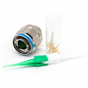
2. Termination: Soldering vs. Crimping
Soldering: Insert the tinned wire into the solder cup. Apply heat to the cup, not the wire, and allow the solder to flow via capillary action. Use heat-shrink tubing over each individual contact to provide additional insulation and strain relief.
Crimping (MS41xx Series): Use a calibrated MIL-spec crimp tool (e.g., M22520 series). Verify the crimp height according to the wire gauge. Crimping is preferred in high-vibration applications as it creates a “cold weld” that is more resistant to mechanical fatigue than solder.
3. Grommet and Backshell Assembly
The Sealing Sequence: Slide the backshell (cable clamp), coupling nut, and sealing grommet onto the cable before termination.
Ensuring IP67 Integrity: For Class F connectors, ensure the grommet is seated firmly against the rear of the insert. The compression of the grommet by the backshell is what creates the environmental seal against moisture ingress.
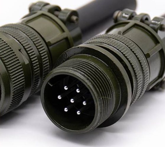
4. Keyway Alignment and Mating
Polarization: The MS5015 features a single large keyway. Align the key on the plug with the slot on the receptacle before attempting to thread the coupling nut.
Torque Application: Hand-tighten the coupling nut until it bottoms out. For critical applications, use a strap wrench to ensure the connector is fully seated, but avoid over-torqueing, which can damage the aluminum threads.
Troubleshooting and Maintenance: Extending Lifecycle in Harsh Environments
Even the most rugged Mil-spec connector requires periodic maintenance to prevent downtime. Below are the most common failure modes and their engineering fixes.
1. Environmental Seal Failure
Symptom: Moisture inside the shell or erratic signal readings.
Cause: Often due to using a cable with an outer diameter (OD) too small for the grommet, or failing to use a bushing (MS3420).
Solution: Always match the cable OD to the bushing size. If the cable is too thin, the cable clamp cannot provide adequate compression for a seal.
2. Contact Corrosion and Oxidation
Symptom: High contact resistance or intermittent power loss.
Cause: Exposure to salt spray or corrosive industrial chemicals without proper plating.
Solution: For coastal or chemical environments, specify Olive Drab Chromate plating (500-hour salt spray rated). Use conductive lubricant on contacts only if specified by the system design, and always use Dust Caps (MS25042/MS25043) when connectors are unmated.
3. High Insertion/Withdrawal Force
Symptom: Difficulty in mating or “grinding” feel during threading.
Cause: Damaged threads or misaligned pins.
Solution: Inspect the coupling threads for debris. Use a dry lubricant if necessary. Check for “bent pins” which occur if the connector is forced together without proper keyway alignment.
Issue
Potential Root Cause
Recommended Action
Intermittent Signal
Cold solder joint or poor crimp
Re-terminate and inspect with pull-test
Thread Galling
Over-torqueing or debris
Clean threads; replace damaged coupling nuts
Moisture Ingress
Incorrect Class (A vs E/F)
Upgrade to Class F with internal grommets
MS5015 Series Frequently Asked Questions
Are MS5015 (Threaded) and VG95234 (Bayonet) connectors interchangeable?
While both series share the same insert arrangements defined by MIL-DTL-5015, they are not intermateable. MS5015 uses threaded coupling, whereas VG95234 uses reverse bayonet coupling. However, backshells and accessories are often compatible.
Can I mate an MS3106 plug from one manufacturer with an MS3102 from another?
Yes. A core benefit of the MIL-DTL-5015 standard is intermateability. As long as they are manufactured to MIL-spec and share the same shell size and insert arrangement, they are designed to be intermateable. For mission-critical applications, we recommend sample validation.
How do I choose between Solder and Crimp contacts?
Solder (MS31xx): Best for low-volume production or field repairs without specialized tools.
Crimp (MS41xx): Ideal for high-volume automated assembly and high-vibration environments, offering better mechanical consistency.
What is the difference between Service Rating “A” and “D”?
This determines the safe working voltage. Service Rating A is rated for 500V AC (RMS), while Service Rating D is a heavy-duty rating for 900V AC (RMS). This rating is determined by the spacing between contacts (creepage/clearance).
Ready to Finalize Your BOM? Partner with a MIL-DTL-5015 Expert
Navigating the complexities of military-grade interconnects requires precision. At Renhotec, we provide more than just connectors; we provide engineering confidence.
Download Datasheets: Access full technical drawings for all MS3100, MS3102, and MS3106 configurations.
As a Product Manager at Renhotec Group (est. 2008), I specialize in providing deep technical insights into connectors, cables, and custom electronic components. Renhotec is a global leader in interconnect solutions, dedicated to manufacturing high-standard products for diverse industries as your trusted technical partner.