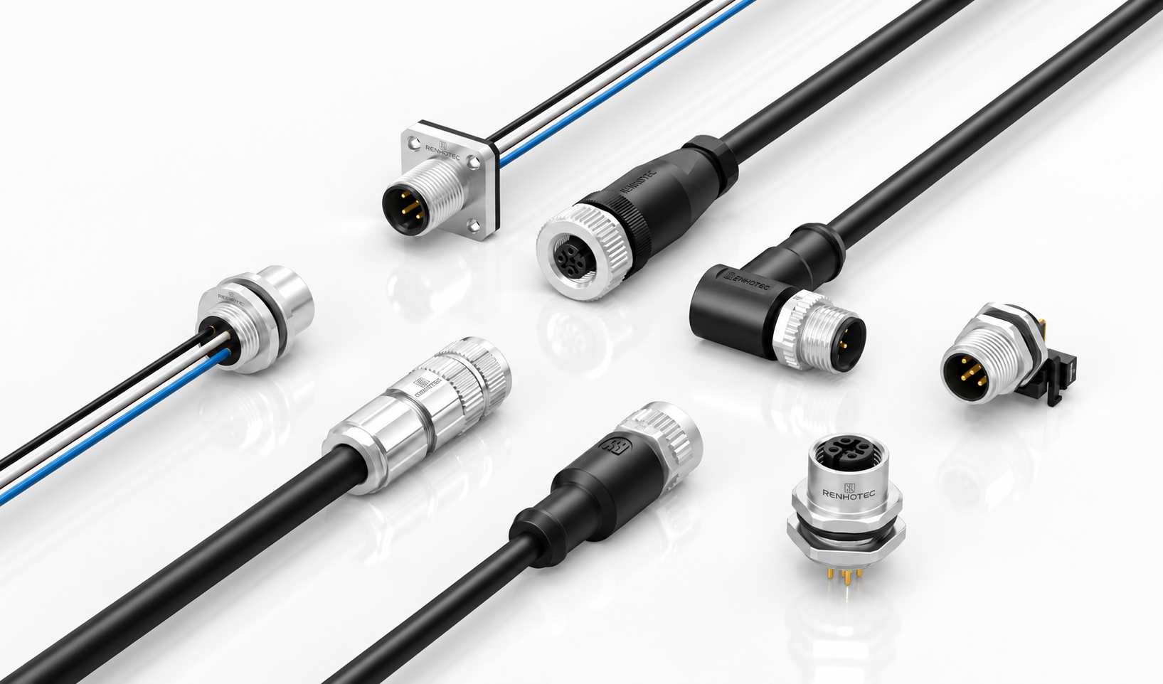
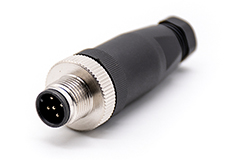
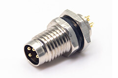
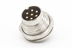
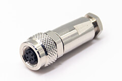
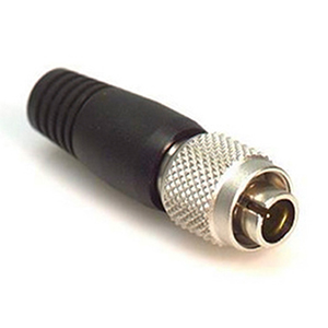
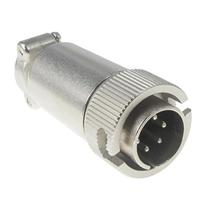
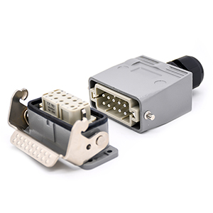
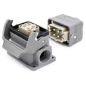
Choose the connection structure

All M12 connectors

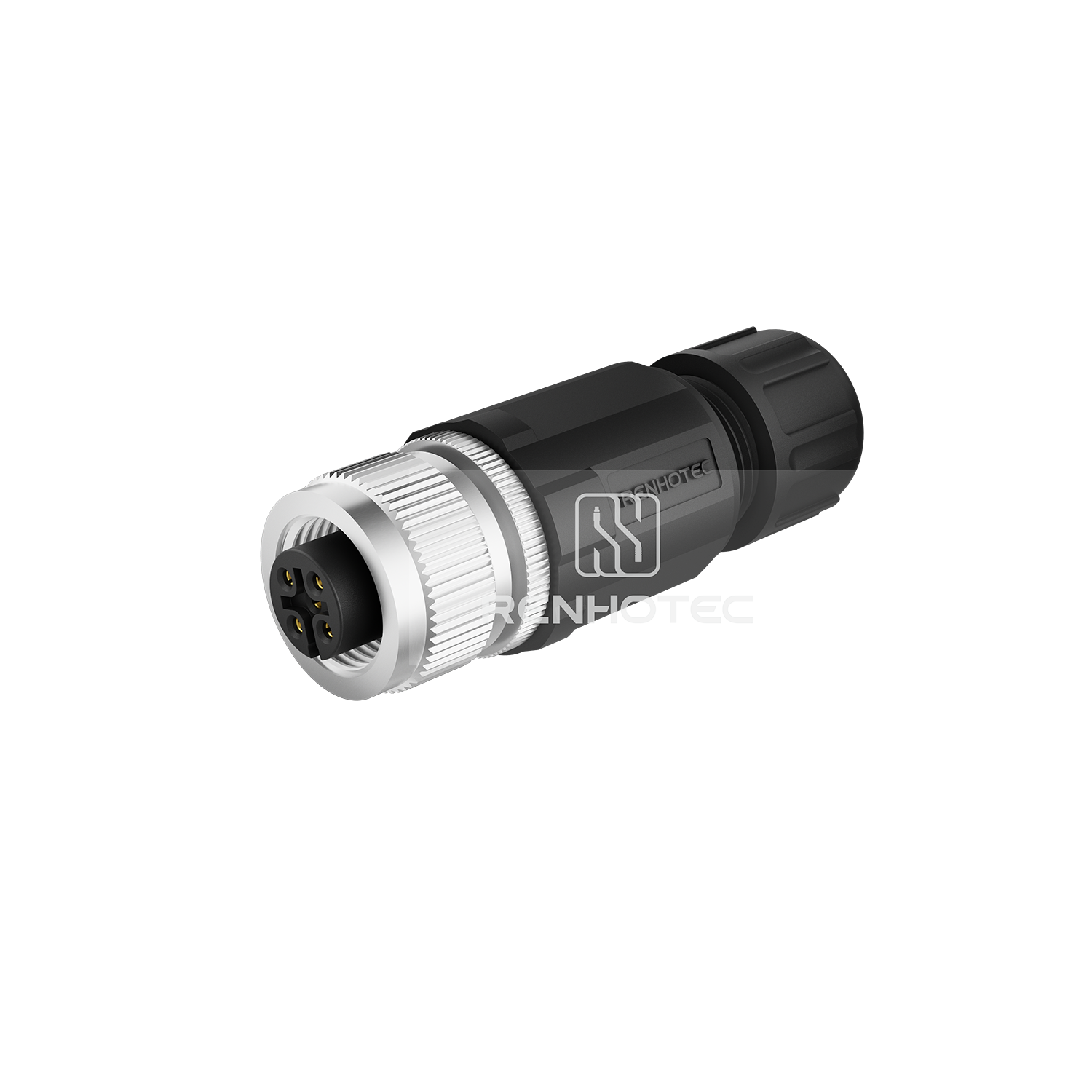
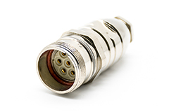
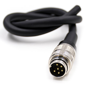
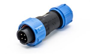
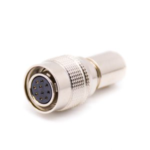
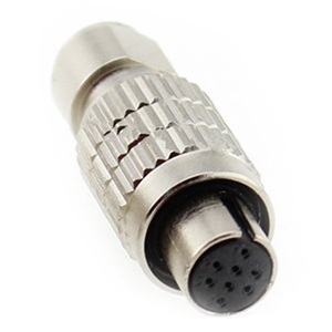
Terminate your own cable.

Screw, solder or crimp
Choose the termination for the conductor and the assembly process. A/B/D families and X-coded connectors have different contact and housing designs.
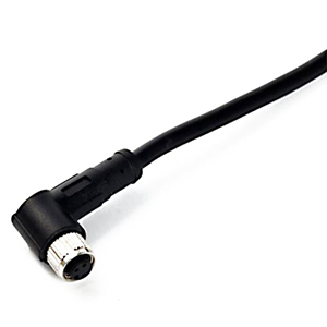
Straight or right-angle
Allow space for the complete backshell, coupling nut and cable bend. Choose the exit direction before routing the cable.
Cable entry & screen
Match cable diameter to the gland. For a shielded design, check how the screen connects to the housing.

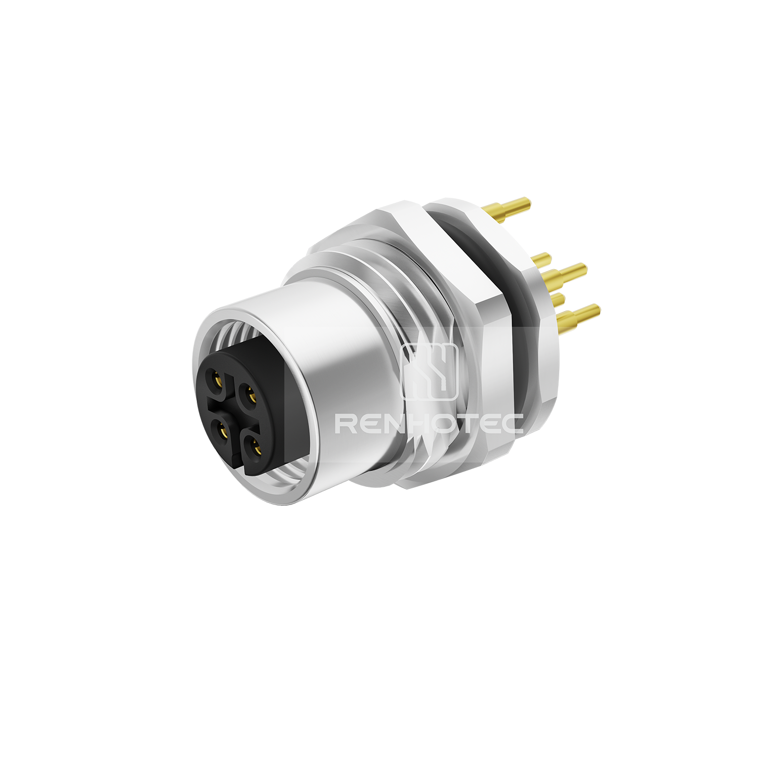
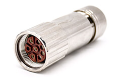
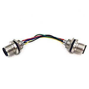
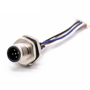
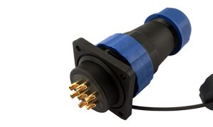
Build the interface into your equipment.

PCB, solder cups or leads
Select the internal termination first. PCB versions need the right footprint, tail length and board-to-panel distance.
Front, rear or flange fastening
Compare the installation direction, panel cutout, wall thickness, sealing face and access to the nut.
Mating thread ≠ mounting thread
M12 × 1 is the mating interface. The panel-side thread and cutout depend on the receptacle design.

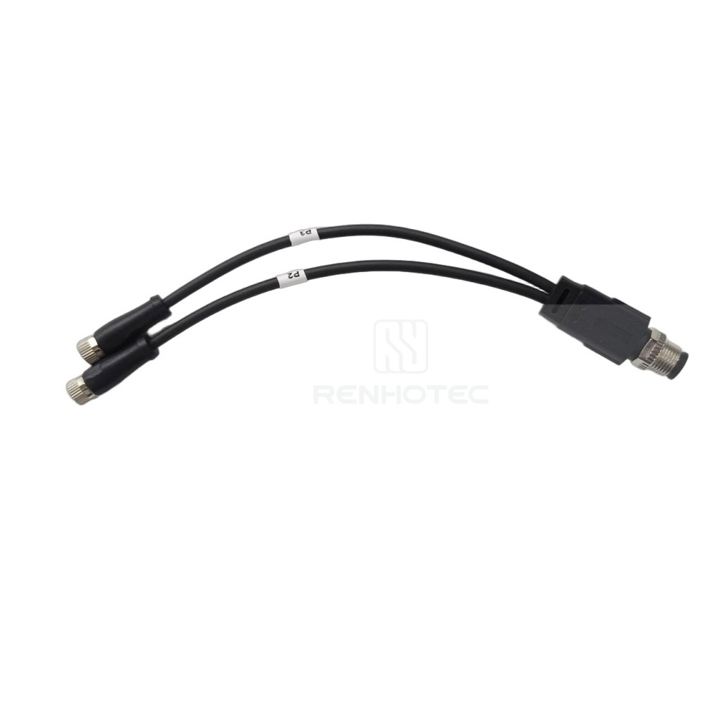
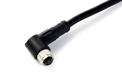
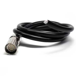
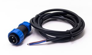
Connect equipment with a finished lead.

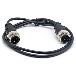
Single-ended or double-ended
Choose free conductors for cabinet wiring, or a connector at each end for a device-to-device connection.
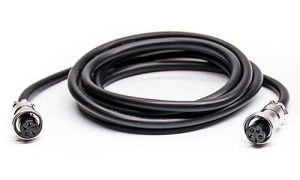
Interface at each end
Specify coding, contacts, gender and exit direction at both ends. A mating-face diagram is not an end-to-end wiring diagram.
Length, jacket & wiring
Use the M12 Cables guide for cable length, PVC/PUR requirements, shielding and a pin-to-pin wiring brief.

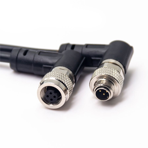
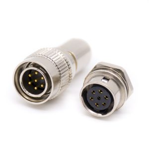
Route, branch or adapt the connection.

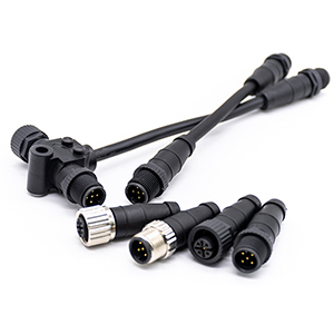
T / Y branching
Define which contacts connect between the main port and each branch. Include the routing space and branch lengths.
Different interfaces
M12-to-M8 and M12-to-RJ45 constructions serve different connection tasks. Choose the exact wiring and equipment interface.
Mechanical clearance
Check every coupling nut, branch direction and adjacent port. A passive adapter does not automatically convert a protocol.

Caps, nuts & sealing accessories

Match the accessory to the selected interface and mounting thread.

Explore accessories

Coding & contact arrangements

Help identify my connector

Sensors & general I/O

Interface reference

A-coded 4 contacts

Female PCB receptacle
RHT-634-1355-04
Male PCB receptacle
RHT-634-1314-04

Get matching parts

Female
Male

5-contact keyed interface

Interface reference

B-coded 5 contacts

Female PCB receptacle
RHT-634-1355-5B
Male PCB receptacle
RHT-634-1314-5B

Get matching parts

Female
Male

4-contact data interface

Interface reference

D-coded 4 contacts

Female PCB receptacle
RHT-634-1355-4D
Male PCB receptacle
RHT-634-1314-4D

Get matching parts

Female
Male

8-contact data interface

Interface reference

X-coded 8 contacts

Female crimp connector
RHT-634-3314-8X
Construction
Shielded · straight · 8 contacts

Get matching parts

Female
Male

Power interfaces

Interface reference

S-coded 3 (2+PE) contacts

Installation
Panel mount or field assembly
Specify with your drawing
Contact marking, current, voltage & termination

Get matching parts

Female
Male

Power interfaces

Interface reference

T-coded 2 contacts

Installation
Panel mount or field assembly
Specify with your drawing
Contact marking, current, voltage & termination

Get matching parts

Female
Male

Power interfaces

Interface reference

K-coded 2 contacts

Installation
Panel mount or field assembly
Specify with your drawing
Contact marking, current, voltage & termination

Get matching parts

Female
Male

Power interfaces

Interface reference

L-coded 2 contacts

Installation
Panel mount or field assembly
Specify with your drawing
Contact marking, current, voltage & termination

Get matching parts

Female
Male

Power interfaces

Interface reference

M-coded 2 contacts

Installation
Panel mount or field assembly
Specify with your drawing
Contact marking, current, voltage & termination

Get matching parts

Female
Male

Contact views and markings follow the catalog. Confirm the selected part drawing before mating.

Open full M12 catalog

Fit the connector to your installation

Ask about a drawing

Panel integration

Mounting geometry
Front / rear fastening or flange; panel-side thread; cutout; wall thickness; nut and O-ring clearance.
Behind the panel
Board position, PCB footprint and tail length, or lead length and internal wire termination.
Electrical interface
Coding, contact count and gender; current and voltage for the exact insert and termination.

Front / rear PCB drawings

Field assembly

Conductor preparation
Choose screw, solder or crimp contacts, then confirm conductor size, strip length and any required assembly tooling.
Cable seal & shielding
Cable outside diameter, gland range, screen termination and housing continuity need to agree with the cable construction.
Installed envelope
Check the complete length, coupling access and cable bend. A right-angle exit can change the required clearance.

Screw / solder drawings

Cables & branches

Every connection end
Define each mating interface, gender and orientation. Branch connections need a complete wiring map.
Routing & support
Installed length, service loops, strain relief, motion and bend radius belong in the cable requirement.
Drawing approval
Check end-to-end wiring and mechanical layout before ordering. Use the M12 Cables guide for a full cable brief.

Adapter & splitter drawings

Compare electrical ratings for one PCB receptacle family

RHT-634-1355 / RHT-634-1314

Front-fastened, straight PCB receptacles — female / male. Catalog ratings for this family.

Interface Contacts Rated current Rated voltage
A-coded / D-coded A: 2 / 3 / 4 · D: 4 4 A 250 V
A-coded / B-coded 5 4 A 60 V
A-coded 6 / 8 2 A 30 V
A-coded 12 / 17 1.5 A 30 V

Open family specification

Drawings & resources

Complete M12 catalog

Field assembly

Screw and solder variants, cable entry and complete housing dimensions.

Open drawings

Panel mounting

Front / rear mounting, part-number tables and dimensioned receptacles.

Open drawings

X-coded connections

8-contact interfaces, shielded assemblies and reference wiring.

Open drawings

Power interfaces

S / T / K / L interfaces and variant-specific electrical tables.

Open drawings

Specifying a complete cable assembly?
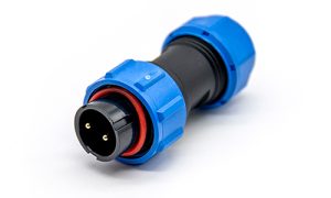
Define both ends, cable length, jacket, shielding and pin-to-pin wiring.
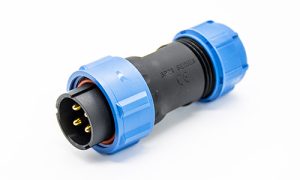
Find the right
M12 connection.

Have a mating part, a drawing or a tight installation space?

Share what you know. We can help check the interface, connector construction and drawing for your project.

  1. The mating interfaceCoding, contacts and gender — or a clear face photo and an existing part number.
  2. The installationPanel fastening, PCB or wire termination, cable diameter and available space.
  3. The operating requirementsVoltage, current, shielding, environment, quantity and required delivery date.

Need a finished cable assembly?

Request a selection & quote


    Up to 3 files · PDF, JPG or PNG · 5 MB per file.


    Interface drawing