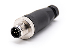
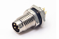
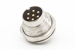
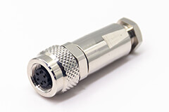
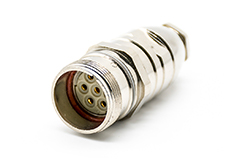
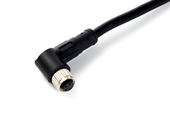
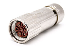
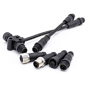
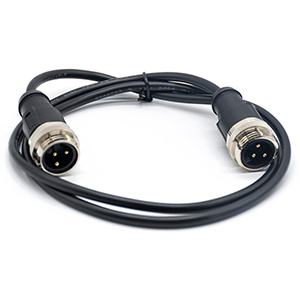
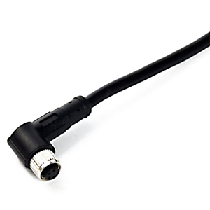
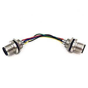
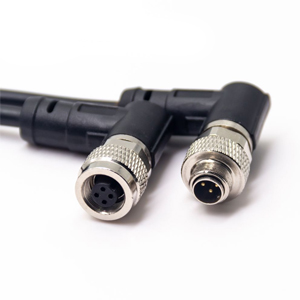
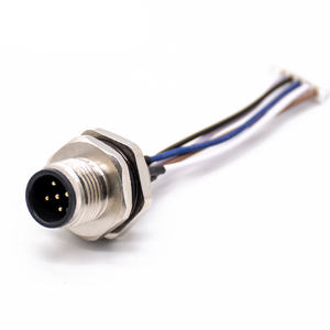
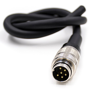
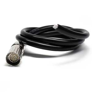
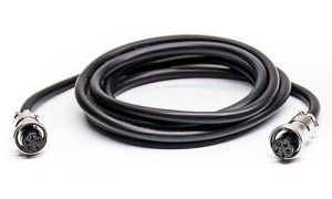
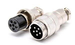
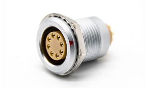
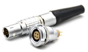
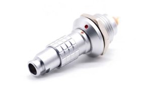
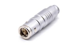
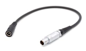
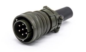
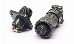
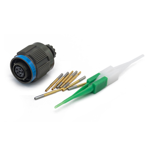
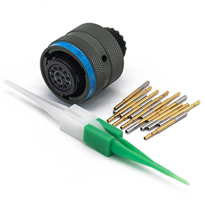
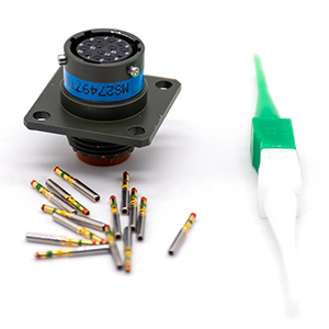
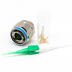
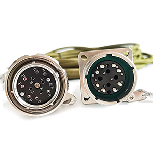
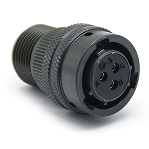
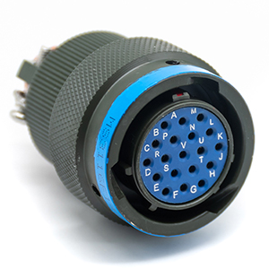
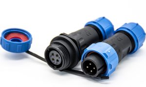
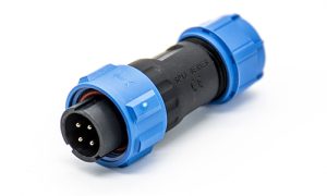
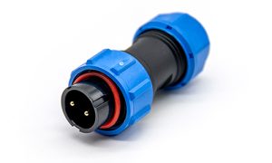
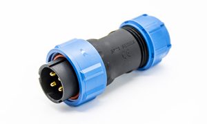
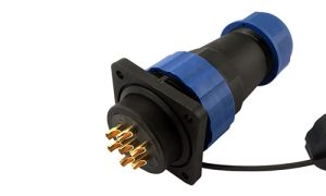
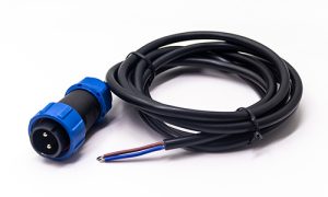
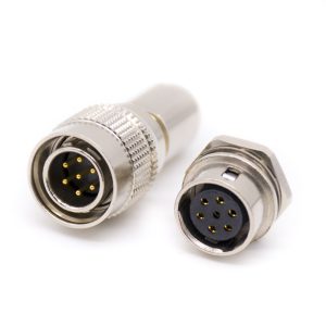
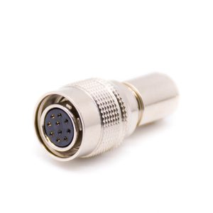
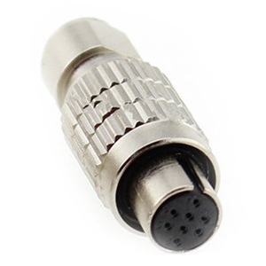
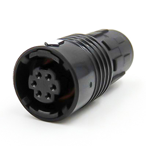
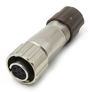
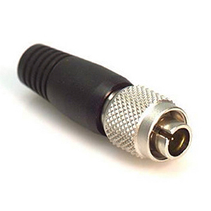
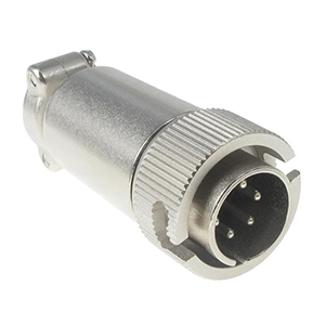
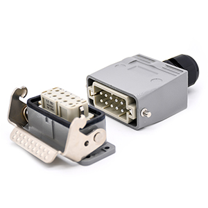
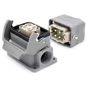
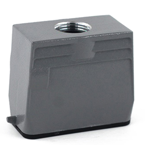
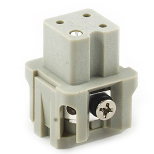
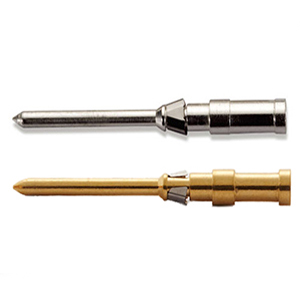
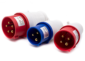
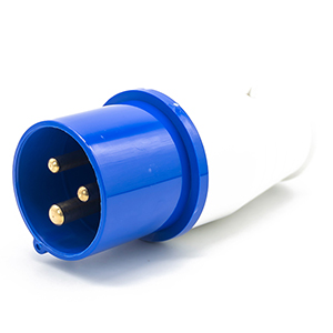
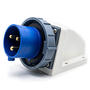
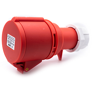
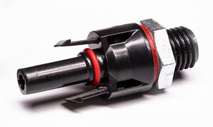
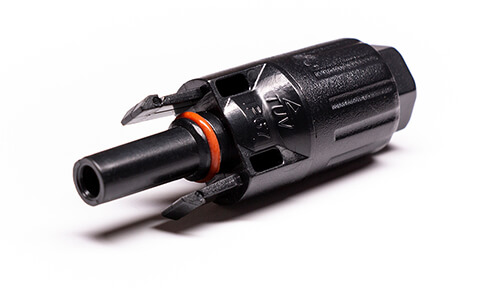
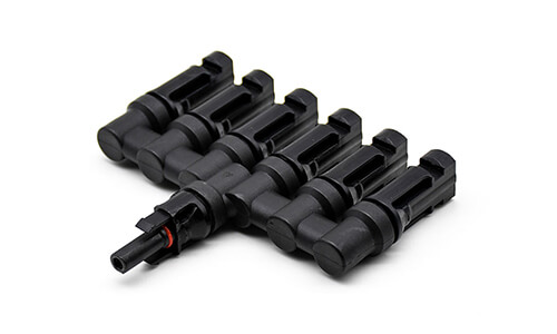
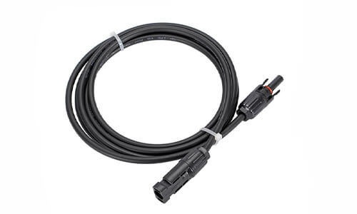
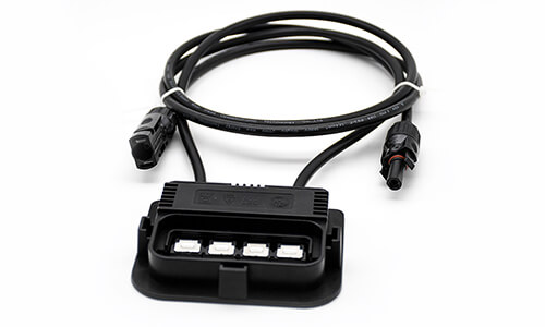
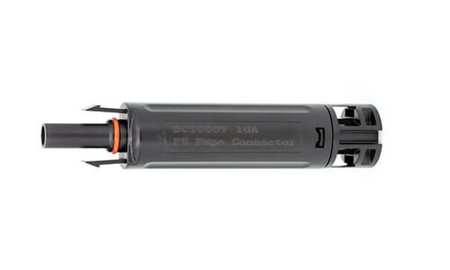
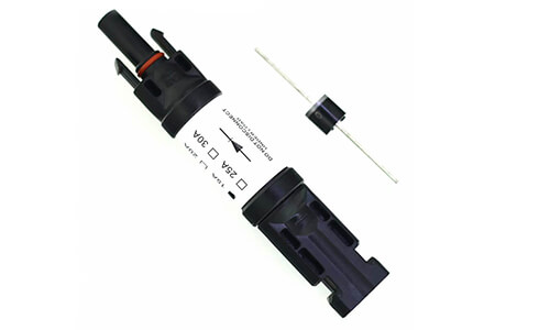
M Series Connectors
Are lightweight triplestart ratchet coupling type connectors designed for avionics, aerospace, Harsh Environment
Connectors, security, motorsport and heavy duty applications.

M-series cable assemblies are widely used in industrial automation, sensor systems, machine vision, and other industrial applications. However, choosing the right assembly involves more than selecting an M8 or M12 connector. Termination methods, IP ratings, cable shielding, connector structures, and customization requirements can all affect compatibility and performance.
This guide answers common questions about M-series cable assemblies to help engineers, equipment manufacturers, and purchasing teams understand their options.
The right termination method depends on the connector design, cable specifications, installation environment, and maintenance requirements. Soldering, crimping, screw termination, and insulation displacement connection (IDC) are four common electrical termination methods, although not every M8 or M12 connector supports all four.
Before choosing a method, check the connector manufacturer’s specifications and assembly instructions. The correct process helps ensure reliable electrical connections and reduces the risk of wiring errors.
Compare the main features of each method before deciding which solution is suitable for your application.

| Termination Method | How It Works | Key Consideration |
|---|---|---|
| Soldering | Joins a wire to a designated contact using solder. | Requires controlled heat and proper soldering technique. |
| Crimping | Secures a wire to a compatible terminal through mechanical compression. | Requires matching terminals, tools, and crimp parameters. |
| Screw Termination | Clamps a conductor inside a terminal using a screw. | Requires correct wire preparation and tightening torque. |
| IDC | Uses a specially designed contact to establish electrical contact through the wire insulation. | Requires a connector designed specifically for IDC technology. |
Solder termination connects a prepared wire to a designated connector contact using solder. The basic process involves preparing the wire, positioning it at the specified contact, applying solder according to the manufacturer’s instructions, and inspecting the finished joint.
Advantages: Soldering can provide a reliable electrical connection when performed correctly.
Limitations: Excessive heat, poor soldering technique, or insufficient mechanical support can damage components or weaken the joint.
When to choose it: Use solder termination only when the connector is specifically designed for soldered contacts and the required tools and process are available.
Crimp termination uses a dedicated tool to compress a compatible metal terminal around a prepared wire. If the connector uses separate contacts, the crimped terminal is then inserted into the connector housing as instructed.
Advantages: Crimping supports repeatable assembly when the correct terminals, tooling, and process parameters are used.
Limitations: An incompatible tool, incorrect wire size, or improper crimp can lead to loose connections or damaged conductors.
When to choose it: Select crimp termination when the connector is designed for crimp contacts and the specified tooling and inspection procedures can be followed.
Screw termination secures a conductor inside a designated terminal by tightening a screw. Depending on the connector design, the installer prepares the wire, inserts it into the terminal, tightens the screw to the specified torque, and checks that the conductor is securely held.
Advantages: It can simplify field wiring and maintenance for connectors designed with screw terminals.
Limitations: Overtightening, undertightening, or incorrect wire preparation may affect connection reliability.
When to choose it: Consider this method when on-site wiring is required and the connector supports screw termination.
Insulation displacement connection (IDC) uses specially designed contacts to establish electrical contact with a conductor through its insulation. The installer positions the insulated conductors in the designated contact arrangement and closes the connector mechanism according to the manufacturer’s instructions.
Advantages: Some IDC designs reduce the need for individual wire-stripping steps and can speed up field installation.
Limitations: Supported conductor sizes, cable construction, and assembly procedures vary by connector.
When to choose it: Use IDC only with connectors and cables specifically approved for this termination technology.
There is no single best termination method for every M-series cable assembly. The most suitable option depends on the connector design and your installation requirements.
Before assembly, consider the connector specification, production volume, installation conditions, available tools, maintenance requirements, and expected electrical performance. Always confirm the approved termination method for the exact M8 or M12 connector model.
Before assembling or ordering an M-series cable assembly, confirm the following details:
Note: Termination options vary by connector model. Always follow the manufacturer’s specifications and assembly instructions. Not every M8 or M12 connector supports all four methods described above.
When choosing an M-series cable assembly for industrial automation, the IP rating helps you understand how well the connector enclosure protects against dust and water. The right rating depends on where the cable will be installed, how it will be used, and whether it may be exposed to water, cleaning, or temporary immersion.
However, an IP rating alone does not guarantee that every assembled connection will remain waterproof. Connector design, sealing components, correct installation, and the conditions under which the rating was tested all matter.
An IP rating classifies protection provided by an enclosure against the entry of solid objects and water. The first digit refers to protection against solid objects, while the second digit refers to water protection.
Provides dust-tight protection and protection against temporary immersion in water under specified test conditions. The standard test commonly involves immersion at up to 1 m for 30 minutes.
Provides dust-tight protection and protection against immersion beyond the IPX7 test conditions, according to conditions specified by the manufacturer. The permitted depth and duration must be confirmed for the particular product.
For many factory automation applications, IP67 may be suitable where connectors face occasional splashes or temporary immersion. IP68 may be needed for applications involving deeper or longer immersion, provided the product is rated for the actual operating conditions.
IP67 is often a practical choice for industrial sensors, actuators, and equipment exposed to dust, splashes, or occasional temporary immersion. However, the right rating depends on the real installation environment.
| Application Condition | What to Consider | Selection Guidance |
|---|---|---|
| Indoor automation | Dust and occasional splashes | IP67 may be suitable |
| Outdoor equipment | Rain, moisture, and temperature changes | Check the full environmental specification |
| Washdown areas | Water jets, cleaning chemicals, and cleaning procedures | Confirm water-jet protection and chemical compatibility |
| Immersion applications | Required depth and exposure duration | Check the manufacturer’s specified IP68 conditions |
Remember that IP67 does not automatically mean protection against powerful water jets, high-pressure cleaning, hot water, or every type of chemical exposure. These conditions require separate consideration.
Yes. Some field-wireable M12 connectors are designed to provide IP67 protection when correctly assembled and used under the manufacturer’s specified conditions. The actual rating depends on the specific connector model and its sealing design.
M12 field-wireable connectors are available in different housing constructions. The following diagrams illustrate plastic-assembled and metal-assembled designs.

Plastic-Assembled M12 Connector

Metal-Assembled M12 Connector
The diagrams show different connector constructions. Housing material alone does not determine the IP rating. Always refer to the specifications of the exact model.
For a field-wireable connector, pay attention to the cable entry seal, cable diameter compatibility, internal sealing components, and the connector’s assembly instructions. Incorrect cable preparation or incomplete tightening can compromise the intended protection.
If the connector is mated to another connector or mounted on equipment, check whether the specified IP rating applies to the unmated connector, the mated connection, or the complete installed assembly.
Not necessarily. A higher water-protection rating can be important for immersion applications, but it does not automatically mean that a connector is better for every industrial environment.
For example, an application involving repeated high-pressure washdown may require verification of water-jet resistance, even if a connector carries an IP68 rating. Similarly, environments with oil, chemicals, vibration, or repeated cable movement may require additional material and mechanical compatibility checks.
Choose the IP rating according to the actual operating conditions rather than selecting the highest number alone.
Correct assembly and installation are essential for maintaining the protection specified for an M-series cable assembly. Follow the product instructions and check the following points before installation.
Do not assume that a connector will retain its rated protection if its sealing components are damaged or the assembly procedure is not followed.
Industrial equipment often operates in environments where electromagnetic interference (EMI) can affect signal quality and communication reliability. A shielded M-series cable assembly can help reduce the impact of electrical noise when it is correctly selected and installed. However, not every M8 or M12 cable assembly requires shielding. The right choice depends on your application, equipment interface, and electromagnetic compatibility (EMC) requirements.
A shielded cable contains a conductive layer, such as metal foil or braided metal, surrounding its internal conductors. An unshielded cable does not include this additional conductive layer. Compare their main differences below.
| Feature | Shielded Cable | Unshielded Cable |
|---|---|---|
| Construction | Includes a conductive shielding layer. | Does not include a dedicated conductive shield. |
| EMI Protection | Can help reduce electromagnetic interference when properly designed and terminated. | Relies on cable design, routing, and the surrounding installation to manage interference. |
| Cost and Installation | May require compatible shielded connectors and appropriate shield termination. | May offer a simpler and more economical configuration where shielding is unnecessary. |
| Typical Selection | Applications with significant electrical noise or defined EMC requirements. | Applications where an unshielded cable meets the equipment specifications. |
A shielded cable assembly combines a cable containing a conductive shielding layer with the required connectors and terminations. The shield may use metal foil, braided wire, or a combination of both, depending on the cable design.
The shield helps reduce the effects of electromagnetic interference on the conductors inside the cable. To achieve the intended performance, the cable shield, connector design, and shield termination must work together as part of the complete connection.
A shielded cable alone does not guarantee immunity to electrical noise. The overall equipment design and installation also matter.
Consider a shielded M-series cable when equipment operates in an electrically noisy environment or when the system has specific EMC requirements.
These are examples rather than mandatory rules. Always check the equipment manufacturer’s specifications and evaluate the actual installation before selecting a shielded cable.
No. Shielding requirements depend on the communication interface, cable specifications, electrical environment, and EMC requirements of the complete system.
Some industrial Ethernet applications specify shielded cabling and compatible shielded connectors. Other applications can use unshielded cables when they meet the required performance and installation conditions. Sensor cables should also be selected according to the sensor and controller specifications.
Before deciding, check the equipment documentation, cable requirements, and applicable installation guidelines. Avoid adding shielding without confirming that the cable and connector configuration are compatible with the system.
Cable shielding should be terminated according to the connector design and the equipment manufacturer’s grounding and EMC requirements. Compatible shielded connectors may provide an electrical path between the cable shield and the connector’s conductive housing.
A properly designed circumferential shield termination can help maintain a short, low-impedance connection, which is particularly important for high-frequency interference.
The correct grounding arrangement depends on the equipment and system design. Connecting the shield at one end or both ends may be appropriate in different applications, so neither approach should be assumed to be universally correct.
If you are unsure, follow the equipment manufacturer’s EMC instructions or consult a qualified engineer before installation.
Shielding options depend on the selected cable, connector design, and assembly configuration. If your application requires a shielded M8 or M12 cable assembly, confirm that the proposed cable and connectors are compatible with your equipment.
When discussing a custom assembly, provide the following information where available:
This information helps the supplier review the required configuration and determine which options are available for the selected M-series product.
Note: Shielding can help reduce electromagnetic interference, but the actual result depends on the complete system design, cable routing, connector compatibility, and shield termination. Confirm the required configuration with the equipment manufacturer before ordering.
M-series connectors are available in different configurations to suit industrial installation requirements. Some are supplied as ready-to-use cable assemblies, some allow on-site wiring, and others are designed to be mounted directly onto equipment panels or enclosures.
Overmolded, field-wireable, and panel-mount describe different aspects of a connection. Understanding their differences helps you select a practical solution for installation, maintenance, and equipment integration.
| Feature | Overmolded Cable Assembly | Field-Wireable Connector | Panel-Mount Connector |
|---|---|---|---|
| Main Purpose | Provides a factory-assembled cable connection. | Allows cable termination during installation. | Provides a fixed interface on a panel or enclosure. |
| Installation | Connect the finished cable assembly to compatible equipment. | Prepare the cable and terminate the conductors on site. | Secure the connector to the equipment panel or housing. |
| Cable Length | Usually specified when ordering, with customization depending on the product. | Can be adapted during installation within the connector’s design limits. | Depends on the cable arrangement connected to the panel interface. |
| Maintenance | Often involves replacing the complete cable assembly if damaged. | May allow on-site retermination when supported by the design. | The fixed interface can remain in place while a compatible mating cable is replaced. |
| Key Consideration | Confirm cable length, connector configuration, and environmental rating. | Check the required tools, wiring procedure, and sealing method. | Verify mounting dimensions, panel thickness, and interface compatibility. |
An overmolded cable assembly has a connector molded directly onto the cable, creating an integrated connection with a protective outer body. The molding can help provide strain relief and protect the cable-entry area.
Key advantages: These assemblies are generally supplied ready to install, reducing the need for on-site wiring and supporting consistent production.
What to consider: Cable length, connector combination, orientation, and other specifications usually need to be confirmed before ordering. If a finished assembly is damaged, replacement of the complete assembly may be necessary, depending on the design.
When to choose it: Consider an overmolded assembly when convenient installation, repeatable assembly, and a factory-prepared cable connection are important.
A field-wireable connector is designed to be terminated and assembled on site using the wiring method specified by the manufacturer. Depending on its design, the cable conductors may be connected through screw terminals, soldered contacts, crimp contacts, or another approved termination method.
Key advantages: It can provide flexibility when cable routing, length, or installation conditions require adjustments on site. Certain designs can also simplify repair or retermination.
What to consider: The installer must follow the correct wiring sequence, use compatible tools, and assemble the sealing components correctly. Improper assembly may affect electrical reliability and the specified IP rating.
When to choose it: Consider this option when field installation flexibility or on-site wiring is a priority.
A panel-mount connector is designed to be fixed to an equipment panel, enclosure, or machine housing. It creates a defined connection interface through which a compatible mating connector can connect to the equipment.
Key advantages: It provides a fixed connection point and can make external equipment connections easier to organize and maintain.
What to consider: Check mounting dimensions, panel thickness, connector orientation, termination style, and the required sealing arrangement. The protection level of the finished installation depends on the connector design and correct mounting.
When to choose it: Panel-mount connectors are suitable when a machine, control cabinet, or enclosure requires a fixed connector interface.
The best option depends on how the equipment is installed and maintained.
These options are not directly interchangeable in every situation. Consider installation time, access for maintenance, available space, environmental exposure, and the cost of replacing or repairing the connection.
Yes. A panel-mount connector can be paired with a compatible overmolded cable assembly when their interfaces match. For example, an industrial machine may have a panel-mounted connection on its enclosure and use a factory-assembled cable to connect external sensors.
Before ordering, verify the connector size, coding, pin count, gender, and mating compatibility at both ends. Also check cable length, orientation, and the required IP rating for the complete connection.
The panel interface, mating connector, and installation must all meet the application requirements. Matching the nominal M8 or M12 size alone does not guarantee compatibility.
Note: Overmolded, field-wireable, and panel-mount describe different connector or assembly characteristics. Their availability, termination options, and IP ratings depend on the specific product design. Always confirm the manufacturer’s specifications before ordering.
A custom M-series cable assembly can be configured to meet specific equipment interfaces, cable routing requirements, and operating conditions. Before requesting a quotation, it helps to define the connector specifications, cable requirements, wiring details, and environmental conditions.
The following questions explain what to prepare when ordering a custom cable assembly and how Renhotec PRO’s customization process moves from initial requirements to production.
Start by specifying the connector size, coding, pin count, gender, and orientation at each end. Also provide the required cable length, jacket material, shielding requirements, and wiring configuration.
If available, share a wiring diagram, technical drawing, equipment interface specification, or reference sample. These details help the engineering team evaluate compatibility and identify a suitable configuration.
Depending on the selected product and design requirements, customization may include cable length, PVC or PUR jacket material, connector combinations, straight or right-angle orientations, and wiring configurations.
Before confirming a design, consider the installation environment, required flexibility, resistance to oil or abrasion, and expected bending conditions. Available options depend on the specific connector and cable design, so confirm the required configuration with your supplier.
A wiring diagram or technical drawing is useful because it identifies the required pin assignments, conductor connections, and equipment interfaces. If a drawing is unavailable, provide the equipment model, connector specifications, and as much information about the existing connection as possible.
A reference sample may also help clarify mechanical dimensions or wiring requirements. The supplier should review the available information before confirming the proposed design.
Before approving a sample or final design, confirm that the proposed assembly matches your agreed specifications. Pay particular attention to connector compatibility, pin assignments, cable length, jacket material, and installation requirements.
Prepare the following information to help your supplier evaluate your requirements more efficiently.
Renhotec PRO follows a six-step customization process to review project requirements, evaluate the proposed solution, validate samples, and prepare for production.
Review the application, essential specifications, and engineering requirements. A mutual non-disclosure agreement can be arranged when needed.
Evaluate the proposed configuration and review relevant technical details or 3D designs where applicable.
Prepare a quotation based on the confirmed specifications, including mold costs when custom tooling is required.
Prepare prototypes and carry out appropriate checks to evaluate the proposed cable assembly configuration.
Validate samples against agreed requirements and provide relevant test documentation as specified for the project.
Proceed to bulk production after sample approval, with quality control according to the applicable requirements.
Explore our M-series connector options for different installation and cable assembly requirements. Select a product category below to review the available configurations.
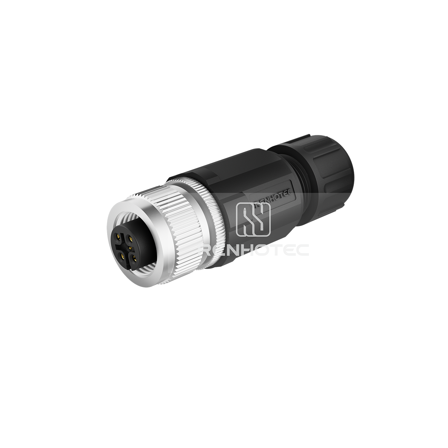
Field Installation
Explore connectors designed for on-site cable termination and flexible industrial installation.
Explore Products
Ready-to-Use Assembly
Browse factory-assembled cable solutions for convenient installation and consistent connections.
Explore Products
Equipment Integration
Find fixed connector interfaces for equipment panels, machine housings, and industrial enclosures.
Explore ProductsShare your connector specifications, cable requirements, wiring diagram, or equipment interface details with Renhotec PRO. Our team can review your project requirements and discuss a suitable cable assembly configuration.
Discuss Your RequirementsNote: Available configurations, customization options, tooling requirements, lead times, and testing arrangements depend on the selected products and confirmed project specifications. Please contact Renhotec PRO to review your requirements.

As a Product Manager at Renhotec Group (est. 2008), I specialize in providing deep technical insights into connectors, cables, and custom electronic components. Renhotec is a global leader in interconnect solutions, dedicated to manufacturing high-standard products for diverse industries as your trusted technical partner.
Add Renhotec as a preferred source on Google