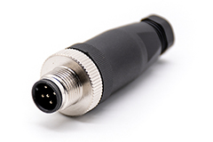
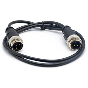
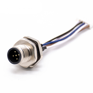
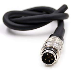
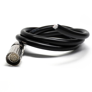
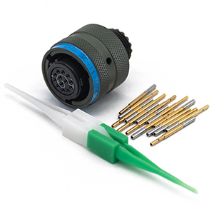
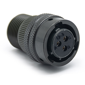
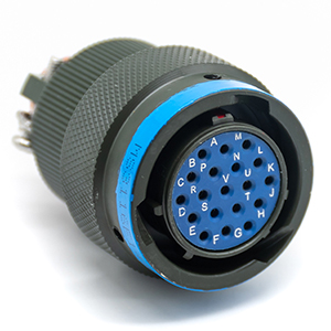
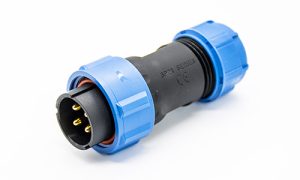
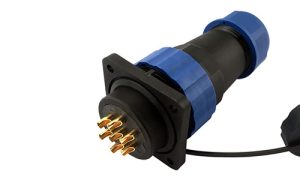
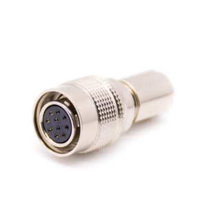
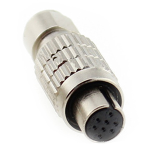
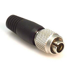
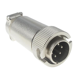
M Series Connectors
Are lightweight triplestart ratchet coupling type connectors designed for avionics, aerospace, Harsh Environment Connectors, security, motorsport and heavy duty applications.
In high-stakes industrial environments—ranging from robotic automotive lines to offshore wind turbines—the interconnect system is often the most vulnerable point of failure. Procurement managers and design engineers face a significant challenge: balancing the initial cost of heavy duty connector assemblies against the long-term risk of unplanned downtime.
A single connection failure due to vibration-induced fretting or ingress of corrosive fluids can halt production for hours, costing thousands of dollars in lost revenue. Sourcing reliable heavy duty wire connectors is not merely a purchase; it is a risk mitigation strategy. The market is saturated with “equivalent” products that may match physical dimensions but fail under thermal cycling or electromagnetic interference (EMI).
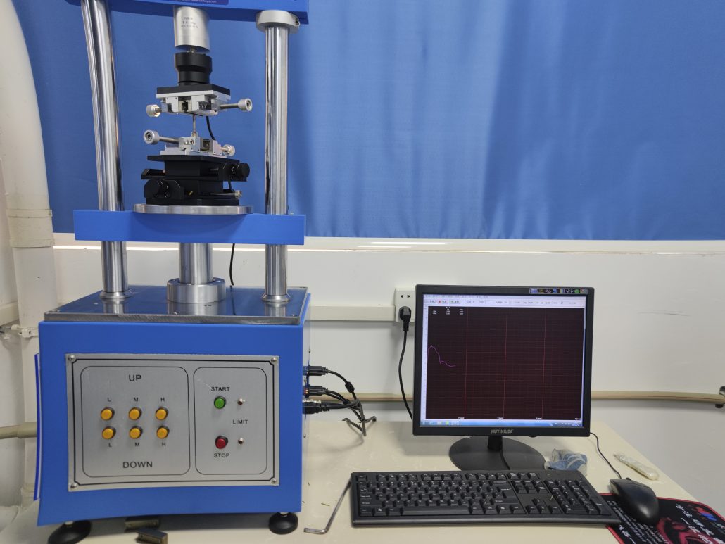
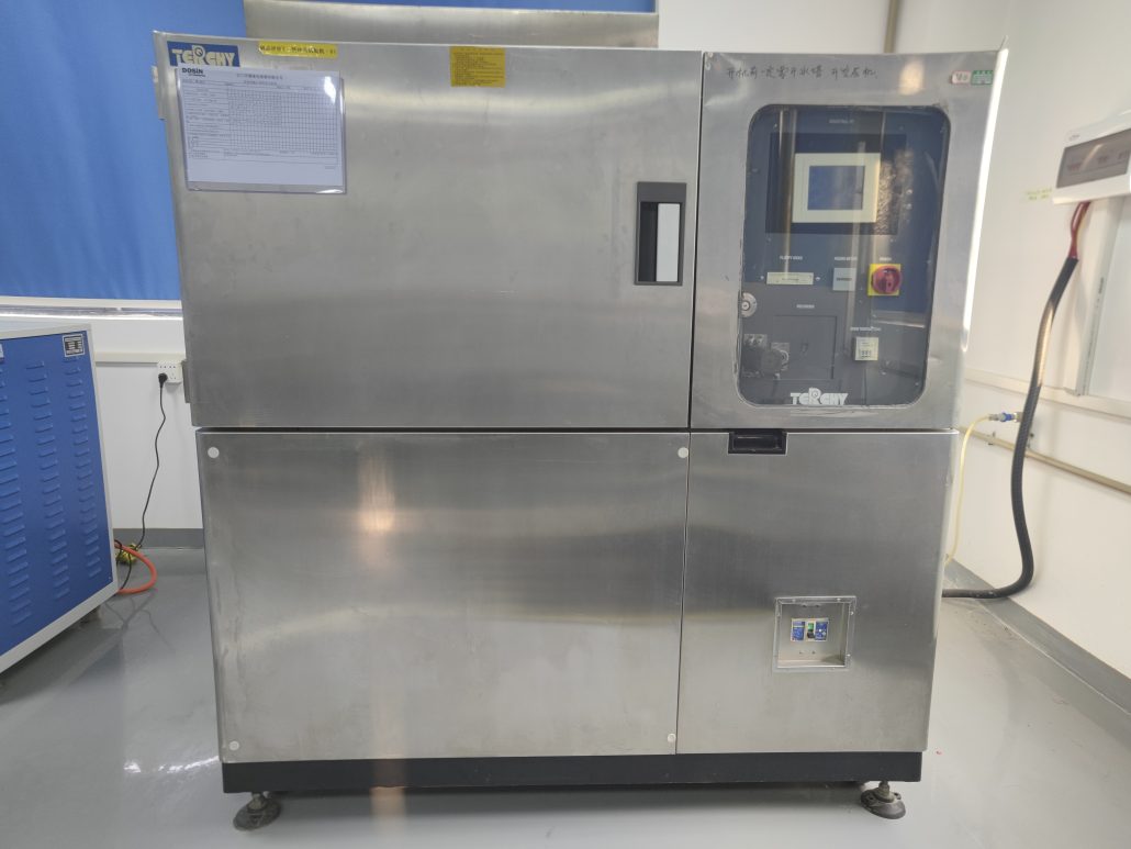
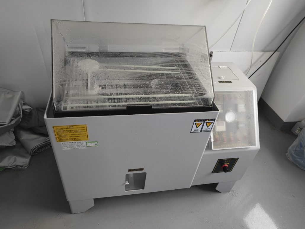
Reliability in a heavy duty connector assembly is not an accidental outcome; it is the result of rigorous engineering validation. When vetting a supplier, looking at a certificate on a wall is insufficient. You must verify that the manufacturer possesses the internal infrastructure to simulate the end-of-life conditions of your equipment.
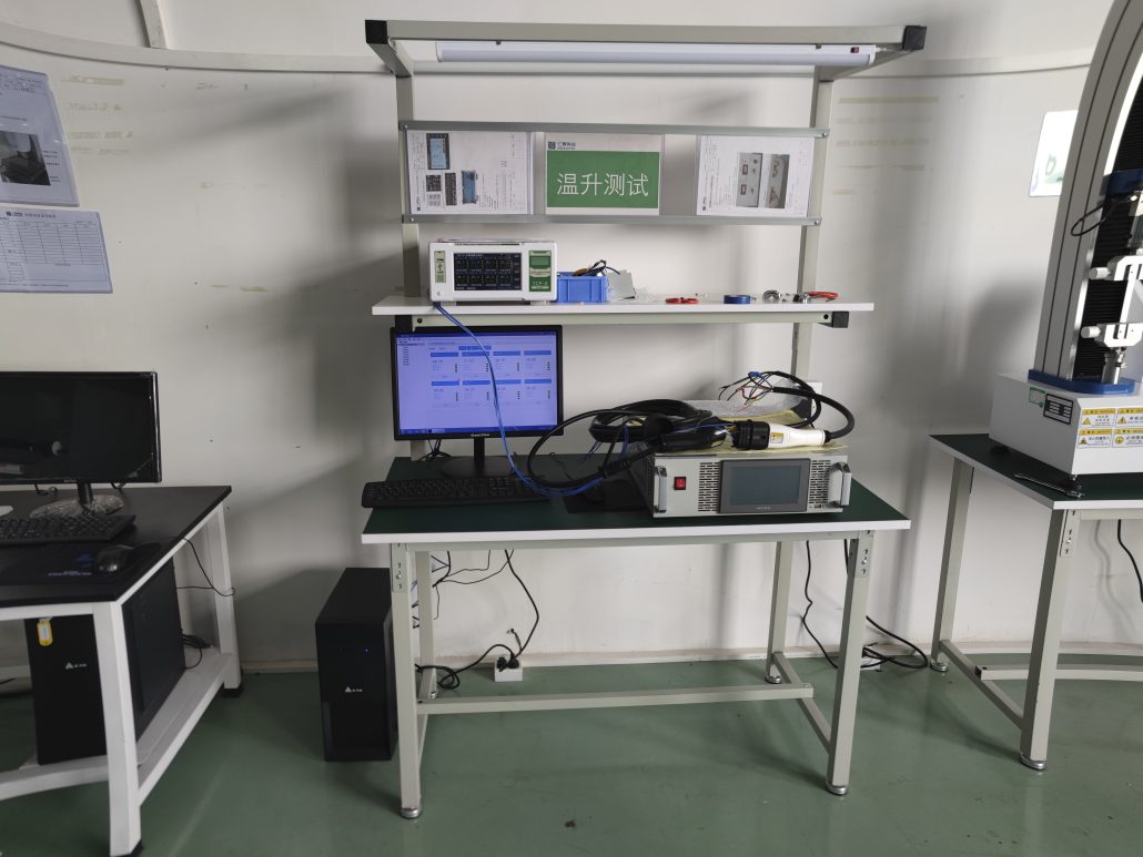
At our facility, every design iteration of our heavy duty wire connectors undergoes a battery of stress tests in our CNAS-aligned laboratory to ensure zero-field failures:
A high-quality supplier must demonstrate control over the entire production lifecycle. Our QC protocol is built on three pillars:
Selecting the correct heavy duty wire connectors requires a systematic approach to electrical and mechanical requirements. The table below outlines the primary considerations for standard industrial applications.
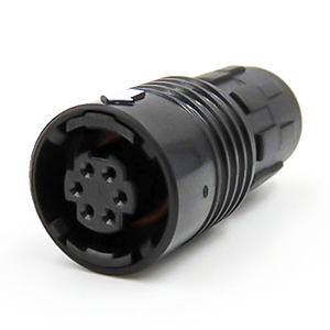
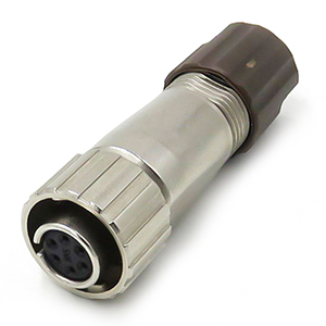
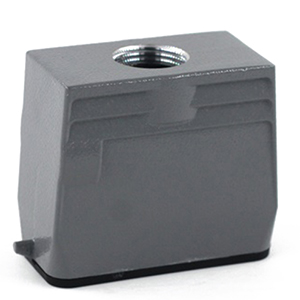
| Feature | Heavy Duty Aluminum Housing | High-Performance Plastic Housing |
|---|---|---|
| Durability | High (Impact & abrasion resistant) | Medium (Lower impact resistance) |
| Weight | Heavier (Die-cast aluminum) | Lightweight (Engineering polymer) |
| EMI Shielding | Excellent (Inherent conductivity) | Poor (Requires special coating) |
| Corrosion Resistance | Good (Powder coated) | Excellent (Inert to most chemicals) |
| Best For | Robotics, CNC, Heavy Machinery | Portable Medical, Food & Bev, Marine |
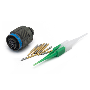
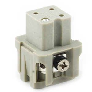
When specifying modular or fixed-pin inserts, use the following checklist:
Proper assembly is as critical as component selection. Even the highest-quality heavy duty connector assemblies will fail if the termination is poor or the seals are misaligned.
Ensure the cable jacket is stripped cleanly without nicking the internal insulation. The strip length must match the terminal depth to prevent exposed copper.
Align the insert with the housing guide rails. Listen for an audible “click” or feel for the positive engagement. Misalignment at this stage is the leading cause of bent pins during mating.
Tighten the cable gland (strain relief) to the specified IP-rated torque. This compresses the internal seal around the cable, preventing moisture ingress.
Engineer’s Note: Always perform a “tug test” on each terminated wire before final housing assembly to ensure mechanical retention.
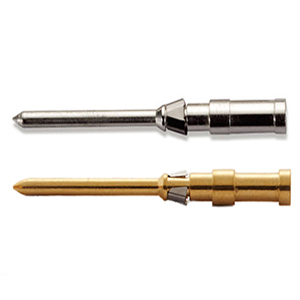
The longevity of heavy duty electrical contacts is determined by the chemistry of their surfaces.
Rehotec provides the engineering expertise and manufacturing precision required for the world’s most demanding environments.

As a Product Manager at Renhotec Group (est. 2008), I specialize in providing deep technical insights into connectors, cables, and custom electronic components. Renhotec is a global leader in interconnect solutions, dedicated to manufacturing high-standard products for diverse industries as your trusted technical partner.