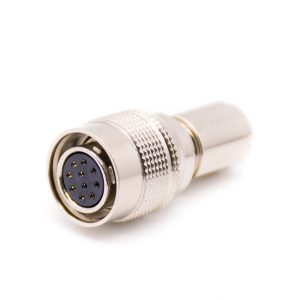
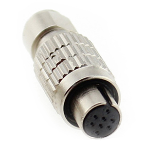
M Series Connectors
Are lightweight triplestart ratchet coupling type connectors designed for avionics, aerospace, Harsh Environment Connectors, security, motorsport and heavy duty applications.
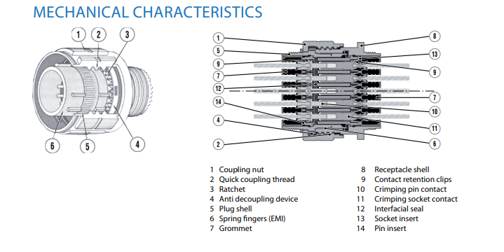
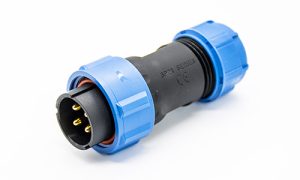
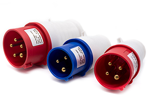
In the realm of aerospace, defense, and high-end industrial applications, the MIL-DTL-38999 Series III connector stands as the gold standard for circular interconnect systems. Originally developed to meet stringent military specifications (MIL-SPEC), these connectors are engineered to maintain electrical integrity under extreme mechanical stress and environmental conditions. The Series III variant is characterized by its high-density contact arrangements and a triple-start threaded coupling mechanism, which provides superior anti-vibration performance compared to traditional bayonet or single-start thread designs.
The robust design incorporates a “scoop-proof” feature, ensuring that pins cannot be damaged during blind mating. For engineers and procurement managers, selecting a D38999 connector means opting for a system that offers 360° EMI/RFI shielding, excellent moisture resistance (up to IP67 or higher when properly sealed), and a wide operating temperature range—typically from -65°C to +200°C depending on the shell plating. At Renhotec, our D38999 compatible solutions undergo rigorous internal laboratory testing to ensure they meet or exceed standard performance benchmarks, providing a cost-effective yet uncompromising alternative to traditional OEM brands.
Key Performance Parameters :
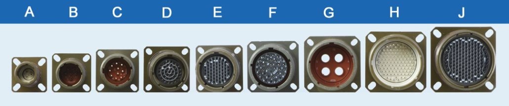
Selecting the correct shell size is the foundational step in any D38999 interconnect design. The MIL-DTL-38999 Series III utilizes a standardized nomenclature where shell sizes are represented by both a numerical value (09 through 25) and a corresponding letter code (A through J). This size directly determines the available “real estate” for contact arrangements and the specific thread interface required for backshells and cable clamps.
The following chart outlines the critical mechanical dimensions for Renhotec’s D38999 series III compatible connectors. Understanding the accessory thread (Thread B) is particularly vital for ensuring compatibility with M85049 backshells.
| Shell Size (Numeric) | Shell Size (Code) | Accessory Thread (Thread B) | Max Diameter (A) |
| 09 | A | M12 x 1.0-6g 0.100R | 15.2 mm |
| 11 | B | M15 x 1.0-6g 0.100R | 18.2 mm |
| 13 | C | M18 x 1.0-6g 0.100R | 21.2 mm |
| 15 | D | M22 x 1.0-6g 0.100R | 25.1 mm |
| 17 | E | M25 x 1.0-6g 0.100R | 28.1 mm |
| 19 | F | M28 x 1.0-6g 0.100R | 31.1 mm |
| 21 | G | M31 x 1.0-6g 0.100R | 34.0 mm |
| 23 | H | M34 x 1.0-6g 0.100R | 37.0 mm |
| 25 | J | M37 x 1.0-6g 0.100R | 40.0 mm |
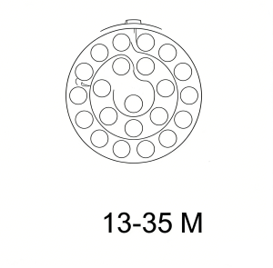
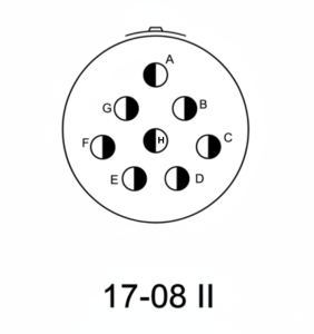
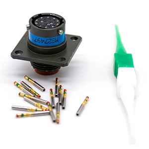
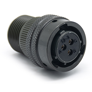
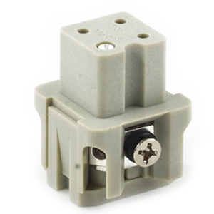
The versatility of the D38999 series lies in its vast array of insert arrangements, supporting everything from high-density signal transmission to high-power distribution. The “pinout” refers to the specific assignment of signals to the numbered cavities within the connector insert. In Series III, these inserts are designed to prevent contact misalignment and offer superior dielectric withstanding voltage.
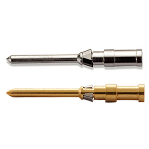
Engineers must match the contact size with the wire gauge (AWG) and current requirements. Common contact sizes used in D38999 pinouts include #22D (the standard for high density), #20, #16, and #12. Each arrangement is identified by a two-part code (e.g., 13-35), where the first part is the shell size and the second is the specific pattern of contacts.
Common Contact Specifications:
Explore Full Technical Specifications & Contact Arrangements
📥 Download D38999 Full Catalog (PDF)File Size: 2.4MB | Format: PDF | Technical Data Sheet
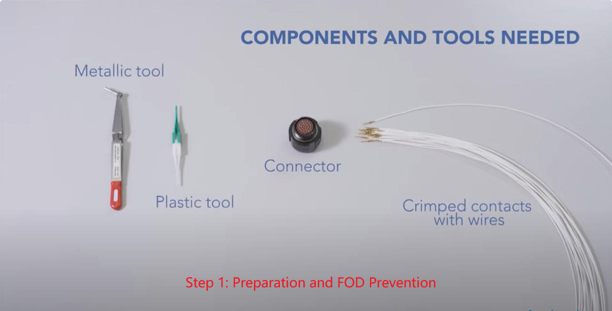
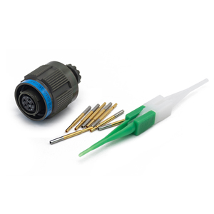
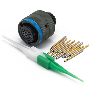
Achieving a reliable, military-grade connection begins with the correct crimping process. Unlike soldering, controlled-cycle crimping provides superior mechanical strength and vibration resistance. For D38999 connectors, the tooling system follows the MIL-DTL-22520 standard. Selecting the right combination of crimp frame and positioner is critical to ensure that the contact’s barrel is deformed precisely without compromising the integrity of the conductor.
Depending on the contact size, engineers typically choose between standard manual crimp tools or specialized insertion/extraction tools. According to industry best practices, while metallic tools offer longevity, plastic tools are often preferred for high-density contacts like #22D and #20 to prevent damage to the connector’s internal grommet and retention clips.
D38999 Tooling Selection Matrix:
| Contact Size | Crimp Tool (MIL-Spec) | Positioner / Turret | Insertion/Extraction Tool |
|---|---|---|---|
| #22D (Signal) | M22520/2-01 (AFM8) | M22520/2-09 | M81969/14-01 |
| #20 (Power/Signal) | M22520/1-01 (AF8) | M22520/1-04 (Red) | M81969/14-10 |
| #16 (Power) | M22520/1-01 (AF8) | M22520/1-04 (Blue) | M81969/14-03 |
| #12 (High Power) | M22520/1-01 (AF8) | M22520/1-04 (Yellow) | M81969/14-04 |
* Note: Plastic tools (M81969/14 series) are recommended for protecting the connector’s internal grommet and gold plating during assembly.
Following a standardized assembly sequence is vital to ensure the long-term reliability of the D38999 system. Any deviation, especially in high-vibration environments, can lead to intermittent signals or catastrophic failure.
Ensure your workspace is clean to avoid Foreign Object Debris (FOD), which can degrade the connector’s performance. Inspect all components—connector body, crimped contacts, and tools—for any visible defects or contamination.
Strip the wire insulation according to the contact’s barrel length. Insert the wire into the contact and use the calibrated M22520 crimp tool. The goal is a “gas-tight” joint that meets the required pull-out force.
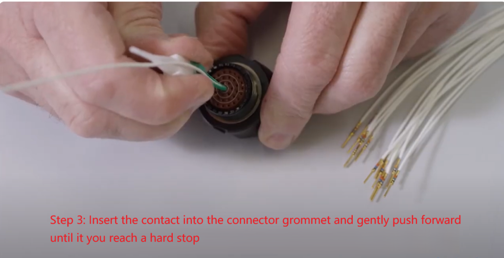
Place the wire into the Insertion side (usually white or colored) of the tool. Hold the cable firmly and push the contact into the connector grommet. You must push forward until you reach a “Hard Stop,” which indicates the retention clip has engaged.
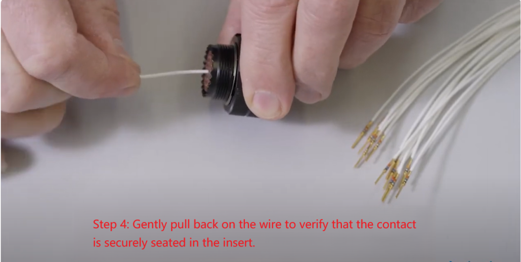
After insertion, performing a light “Pull Test” (3-5 lbs of force) is mandatory. Gently pull back on the wire to verify that the contact is securely seated in the insert. If it moves, re-insert or inspect the retention clip.
Thread the backshell onto the accessory threads (refer to the Shell Size Chart). Ensure the backshell is torqued to the manufacturer’s specifications to maintain environmental sealing and strain relief.

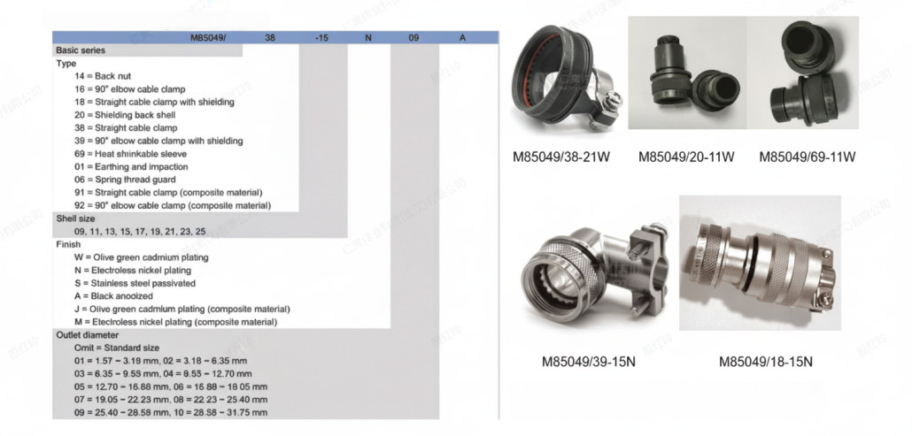
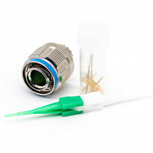
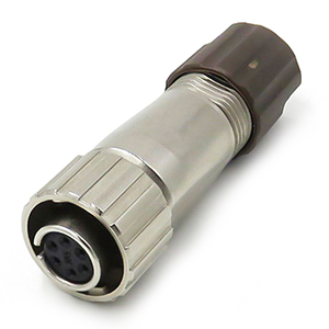
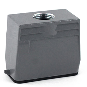
The backshell is the final line of defense for a D38999 connector assembly. Its primary functions are to provide strain relief for the wire bundle and to maintain the continuity of the EMI/RFI shielding. According to the M85049 standard, backshells are selected based on the environment (e.g., sea spray, high vibration) and the cable exit angle required for the system layout.
The backshell is the final line of defense for a D38999 connector assembly. Its primary functions are to provide strain relief for the wire bundle and to maintain the continuity of the EMI/RFI shielding. According to the M85049 standard, backshells are selected based on the environment (e.g., sea spray, high vibration) and the cable exit angle required for the system layout.
For most aerospace applications, the M85049/38 (Straight) and M85049/39 (90-degree) cable clamps are the industry defaults. However, for high-interference environments, a shielding backshell (e.g., M85049/21) with a 360° screen termination is essential to prevent signal degradation. At Renhotec, we provide both aluminum and composite backshells to balance weight and corrosion resistance.
While metal tools are more durable, they carry a higher risk of damaging the connector’s internal retention clips and the thin gold plating on smaller contacts (size #22D and #20). We recommend using plastic M81969/14 tools for high-density arrangements to ensure a “soft” install and prevent FOD (Foreign Object Debris).
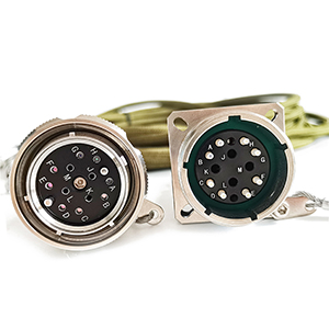
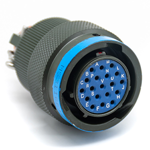
On the face of the insert, look for the master keyway (the widest notch on the shell). Position 1 is typically located at the top center or slightly clockwise from the master keyway, depending on the specific arrangement. Always refer to the technical catalog for exact numbering.
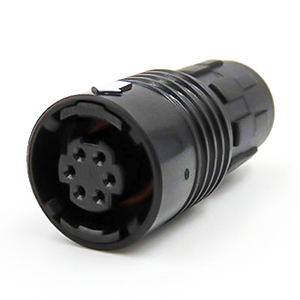
Series III uses a Triple-start Threaded coupling with self-locking, ideal for high-vibration. Series I uses a bayonet coupling for quick mating, and Series II is a low-profile version for weight-sensitive applications. Note that shells are not intermateable across different series.
Looking for comprehensive technical data and dimensions?
📥 Download Full D38999 Catalog (PDF)Includes Cross-Reference, Shell Charts & Custom Solutions
As a leading global supplier of high-performance interconnect solutions, Renhotec specializes in the design and manufacture of MIL-DTL-38999 Series I, II, and III connectors. Our products are engineered to meet the rigorous demands of aerospace, defense, and industrial automation, ensuring uncompromising reliability in the most mission-critical environments. By maintaining an extensive inventory of shell sizes, insert arrangements, and specialized crimp tooling, Renhotec provides the rapid lead times and technical support that modern engineering projects require.
Whether you are looking for cross-references for major OEM brands, custom cable assembly services, or high-volume procurement support, our team of application engineers is ready to assist. We don’t just supply components; we provide the technical expertise to ensure your interconnection system is optimized for performance and durability.
Contact our sales and engineering team today for a competitive quote or to discuss your specific design requirements. We are committed to being your most responsive and reliable D38999 connector supplier.
Email: [email protected]
Website: www.renhotecpro.com

As a Product Manager at Renhotec Group (est. 2008), I specialize in providing deep technical insights into connectors, cables, and custom electronic components. Renhotec is a global leader in interconnect solutions, dedicated to manufacturing high-standard products for diverse industries as your trusted technical partner.


 Русский