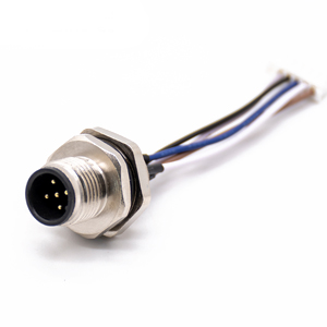
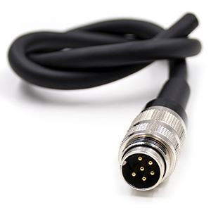
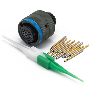
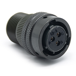
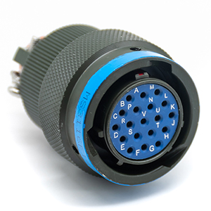
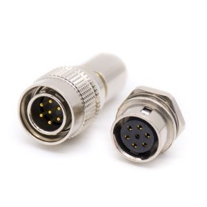
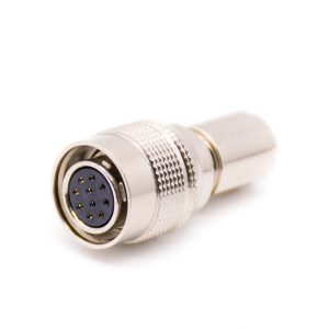
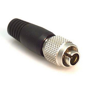
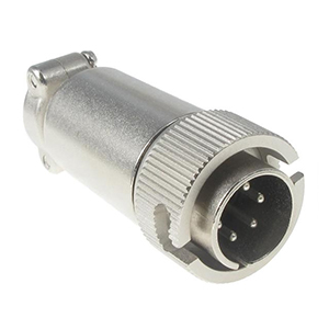
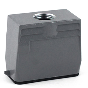
M Series Connectors
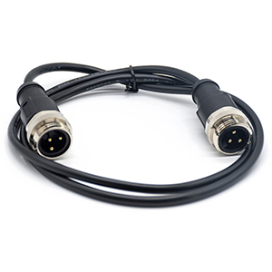
Are lightweight triplestart ratchet coupling type connectors designed for avionics, aerospace, Harsh Environment Connectors, security, motorsport and heavy duty applications.
The 5 Pin DIN connector is one of the most recognizable interfaces in electronics history. While it is universally associated with the 5 pin din midi cable used in music production, its application extends far beyond synthesizers into industrial automation, medical devices, and power supply systems. However, a common misconception is that all “5 Pin DIN” connectors are identical.
Engineers and procurement officers frequently encounter a frustrating problem: a newly purchased connector fits the diameter but physically refuses to mate with the socket. This is often due to the subtle but critical differences in pin configuration angles. Choosing the wrong layout can lead to project delays, connector damage, or signal failure. This guide will clarify the differences between 180°, 240°, and 270° layouts and provide industrial-grade selection criteria to ensure you specify the exact component required.
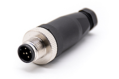
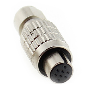
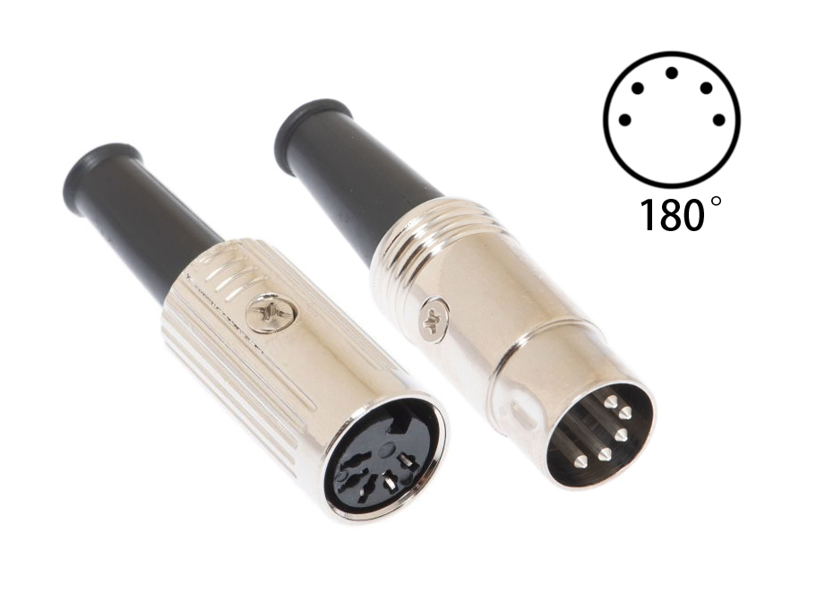
A DIN connector is an electrical connector that was originally standardized by the Deutsches Institut für Normung (German Institute for Standardization) in the 1970s. The standard 5-pin version features a circular metal shield with a diameter of approximately 13.2mm, surrounding a circular insert where the pins are located (DIN 41524 / IEC 60130-9).
The connector is favored in both consumer and B2B sectors because the circular metal shell provides excellent structural protection and electromagnetic shielding. However, the arrangement of the five pins varies significantly depending on the intended use.
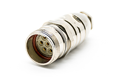
The most significant specification to verify is the angular distribution of the pins. This is not about the rotation of the plug, but the arc over which the pins are spread.

For the vast majority of users searching for din 5 connector pinout, the context is MIDI (Musical Instrument Digital Interface). The MIDI Association strictly defines this standard to ensure compatibility across all devices.
| Pin Number | Function (MIDI) | Wire Color (Typical) |
| Pin 1 | Not Connected (NC) | N/A |
| Pin 2 | Shield / Ground | Bare/Black |
| Pin 3 | Not Connected (NC) | N/A |
| Pin 4 | Source (Current +) | White/Red |
| Pin 5 | Sink (Current -) | Red/Black |
Note: In modern Type A and Type B TRS-to-MIDI adaptations, these pin assignments remain critical for signal integrity.
In industrial environments utilizing 240° or 270° connectors, there is no universal standard. A 5-pin connector on a CNC machine might use Pin 1 for +24V Power and Pin 5 for Ground, whereas a medical device might use the same pins for data Rx/Tx.
Critical Warning: Never assume the pinout of a 240°/270° connector based on color codes. Always consult the OEM datasheet or the wiring diagram provided by the manufacturer (e.g., Renhotec or device manuals) before soldering.
When selecting 5 Pin DIN Connectors for industrial or harsh environments, audio-grade specifications are often insufficient. Based on industrial connector standards, consider the following factors:
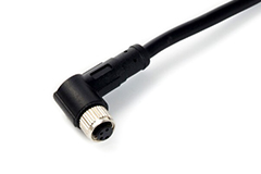
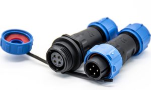
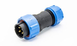
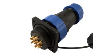
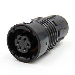
Standard DIN connectors utilize a friction-fit metal shield which offers no protection against moisture. For factory automation or outdoor sensors, you must select connectors with appropriate IP Ratings (Ingress Protection).
A standard DIN plug is held in place only by the friction of the outer shell. In high-vibration environments (e.g., robotics, vehicle telematics), this can lead to intermittent signal loss.

The 180° layout remains the backbone of the music industry. It connects keyboards, synthesizers, drum machines, and audio interfaces. High-quality 5 pin din midi cables with braided shielding are essential here to prevent radio frequency interference (RFI) in studio settings.
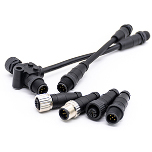
The 240° and 270° layouts are prevalent in:

Q: Can I use a 240° and 270° DIN connector interchangeably?
A: No. Although the difference seems slight, the pin pitch (spacing) is different. Forcing a 240° plug into a 270° socket will bend the pins and damage the equipment.
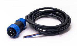
Q: Can a 5 Pin DIN MIDI cable transmit power?
A: Standard MIDI cables are designed for data, not power. While Pins 4 and 5 carry current in the loop, they are not designed to power external devices. If you need to transmit power (e.g., Phantom Power over MIDI), ensure you are using a cable specifically rated for the required amperage.
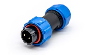
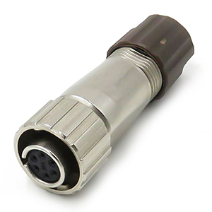
Q: What is the best shell material for industrial use?
A: Die-cast zinc alloy or nickel-plated brass is recommended for industrial applications. These materials offer superior durability and EMI shielding compared to plastic or thin stamped metal shells.
Need assistance selecting the perfect 5 Pin DIN Connector for your specific industrial or audio application?
Explore our full range of metal-shell, high-reliability 5 Pin DIN Connector solutions.
Or, please contact our engineering team [email protected] for a free consultation and customized quote based on your exact electrical and environmental specifications.

Sharing insights on connectors and real-world applications.
Contact for datasheets, samples, or inquiries.