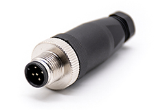
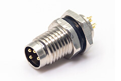
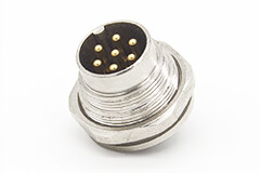
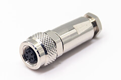
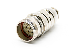
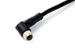
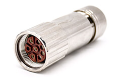
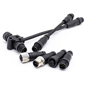
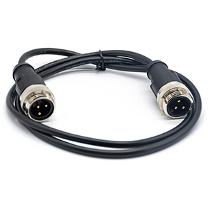
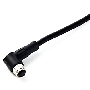
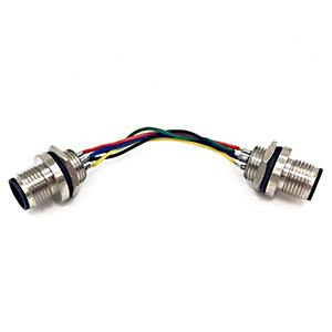
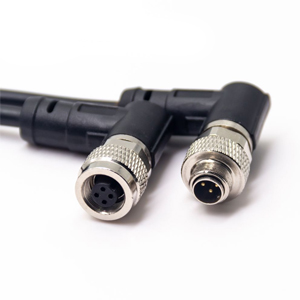
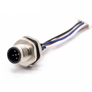
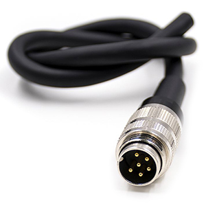
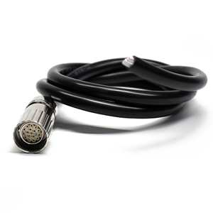
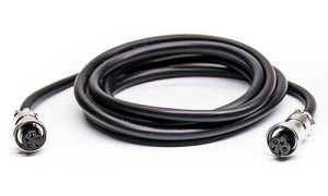
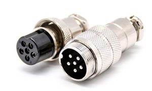
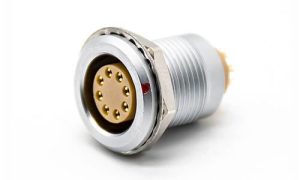
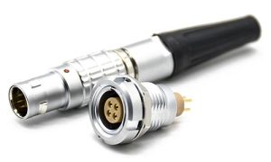
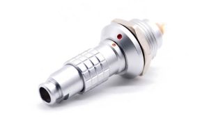
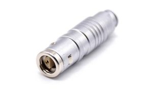
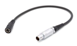
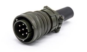
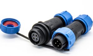
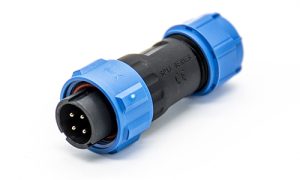
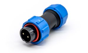
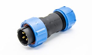
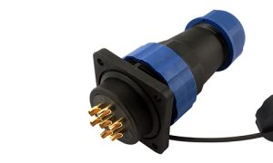
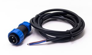
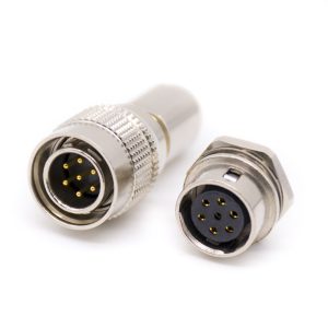
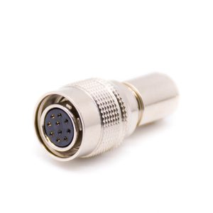
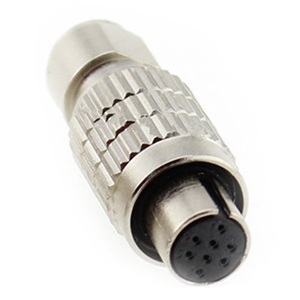
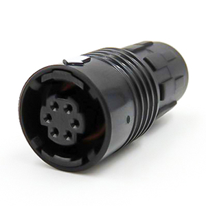
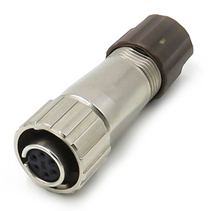
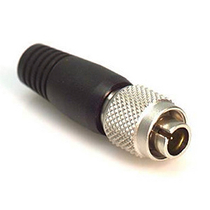
M Series Connectors
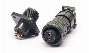
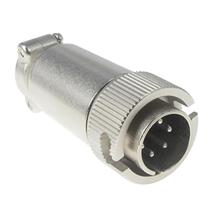
Are lightweight triplestart ratchet coupling type connectors designed for avionics, aerospace, Harsh Environment
Connectors, security, motorsport and heavy duty applications.

Two questions decide this before anything else. Will the connector live inside a sealed enclosure, or will it see weather? And what has to pass through it — how many signals, and how thick is the cable?
The B and K series answer the first question differently. The shell sizes answer the second. Everything on this page is arranged so you can settle both in a few minutes and leave with a part number.
Both series share the same push-pull latch, the same insert layouts and the same contact options. What changes is the housing — and therefore where the connector is allowed to go.
| B series | K series | |
|---|---|---|
| Where it goes | Indoor equipment, protected enclosures | Outdoor, wet, washdown, temporary immersion |
| Sealing | IP50 dust protected, not water resistant | IP68 mated / IP66 unmated |
| Shell range | 00B, 0B, 1B, 2B, 3B | 0K, 1K, 2K, 3K |
| Keying | 13 options — key G standard, plus A–M and R | 9 options — key G standard, plus A–F, L and R |
| Temperature | −55 to +250 °C | −55 to +250 °C |
Read the sealing row twice. B series is IP50: it keeps dust out and does nothing about water. That is not a weakness — inside a cabinet it is the correct and cheaper choice. K series reaches IP68 only when mated, and sits at IP66 when the halves are apart. In storage, or on a panel before the plug goes on, it is not submersible.
The next section is where most projects go wrong: the number in front of B and the number in front of K are not the same size.
A 1B and a 1K look like the same part in two finishes. They are not. The K series carries an additional sealing stack, so every K number sits roughly one and a half shell sizes above its B counterpart.

If you are comparing the two ranges on the fly, remember the offsets: 0K falls between 1B and 2B, 1K between 2B and 3B, 2K between 3B and 4B.
Working out the right shell takes three inputs, in this order. Skipping the first one is the usual reason a cable will not fit.
Sets the minimum contact size.
Sets the insert configuration.
Sets the collet code.
Here is the whole thing on one real cable. Six signal cores at 0.5 mm², jacket measuring 6.0 mm. Six cores point to a six-contact insert. A 6.0 mm jacket takes a D62 collet. Both land inside the 1B shell — 12.1 mm panel hole, M12×1.0 thread, D-type collet. Specify it as EGG.1B.306.CLL for a fixed socket with female solder contacts.
Panel cut-out and thread are the two numbers your mechanical drawing has to carry. Contact counts and collet codes are starting points for each shell.
| Shell | Cut-out Ø | Panel thread | Contacts | Collet code | |
|---|---|---|---|---|---|
| 00B | 7.1 mm | M7×0.5 | 2–4 | D27 / D32 | View |
| 0B | 9.1 mm | M9×0.6 | 2–9 | D32 / D42 | View |
| 1B | 12.1 mm | M12×1.0 | 2–14 | D42 / D52 / D62 | View |
| 2B | 15.1 mm | M15×1.0 | 2–19 | D62 / D72 / D82 | View |
| 3B | 18.1 mm | M18×1.0 | 2–32 | D82 / D92 / D99 | View |
| 0K | 14.1 mm | M14×1.0 | 2–9 | C or K type | View |
| 1K | 16.1 mm | M16×1.0 | 2–14 | C or K type | View |
| 2K | 20.1 mm | M20×1.0 | 2–19 | C or K type | View |
| 3K | 24.1 mm | M24×1.0 | 2–32 | C or K type | View |
Collet codes read as cable diameter: D42 takes a 4.2 mm jacket, D62 takes 6.2 mm. Pick the code that matches the jacket, not the one that matches the shell number.
If your panel hole is already cut, work backwards from the two left-hand columns. If it is not cut yet, choose the shell from the cable and stay inside the series that suits the environment.
Six things hold true across every shell size and both series. They are also the reason these connectors end up on camera rigs and operating tables rather than in a junction box.
Push to lock, pull the outer sleeve to release. No twisting. Rated 10–2000 Hz at 15 g.
Full-perimeter shield, >80 dB at 1 GHz, >95 dB at 10 MHz.
13 keyways on B, 9 on K — similar plugs cannot cross-mate.
>5,000 cycles. Ten insertions a day for well over a year.
Brass shell, PPS insulator; PSU, PPSU and PEEK for sterilisation.
Coax, fibre, high voltage, fluidic and multipole in one shell.
Each card gives the setup, the part that usually fails, and how the connector is actually mounted and wired.
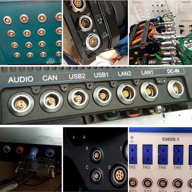

Once you can read one, the catalogue stops being a wall of text. Take the code below apart from left to right.
The 3 in 306 marks the multipole insert family; the last two digits are the contact count, so 310 is a ten-way and 332 is a 32-way. The final group tells you the sex and the termination: CLL is female solder, CLA is male solder. Change one letter and you have a different connector, which is why we confirm the full string before quoting.
Sockets — EGG fixed socket with nut / EEG PCB mount / ECG right-angle / EBG solder panel / PHG with cable collet
Plugs — FGG straight / FHG right-angle / FAG panel mount / FNG cable mount
Mating a 1B plug to a 1K socket
Same number, different shell. K runs about 1.5 sizes larger.
Choosing by contact count, ignoring the jacket
The jacket sets the collet, and the collet decides whether it assembles at all.
Assuming a K series is sealed on the shelf
IP68 only when mated. Apart, it is IP66.
If your cable is already made, send us the jacket diameter and contact count and we will do the lookup for you.
Send your cable diameter and contact count, and we will come back with a shell, a part number and a price — usually within one working day.
Browse the push-pull range →Add Renhotec as a preferred source on Google