M Series Connectors
Are lightweight triplestart ratchet coupling type connectors designed for avionics, aerospace, Harsh Environment Connectors, security, motorsport and heavy duty applications.
General power connectors are specifically designed to transfer power from one device to another or from one point to another point in the same device. This type of connector usually has relatively high voltage, current, and temperature ratings. Let’s explain the next common power connector, called DC power connector.
Overview of DC power connector knowledge:
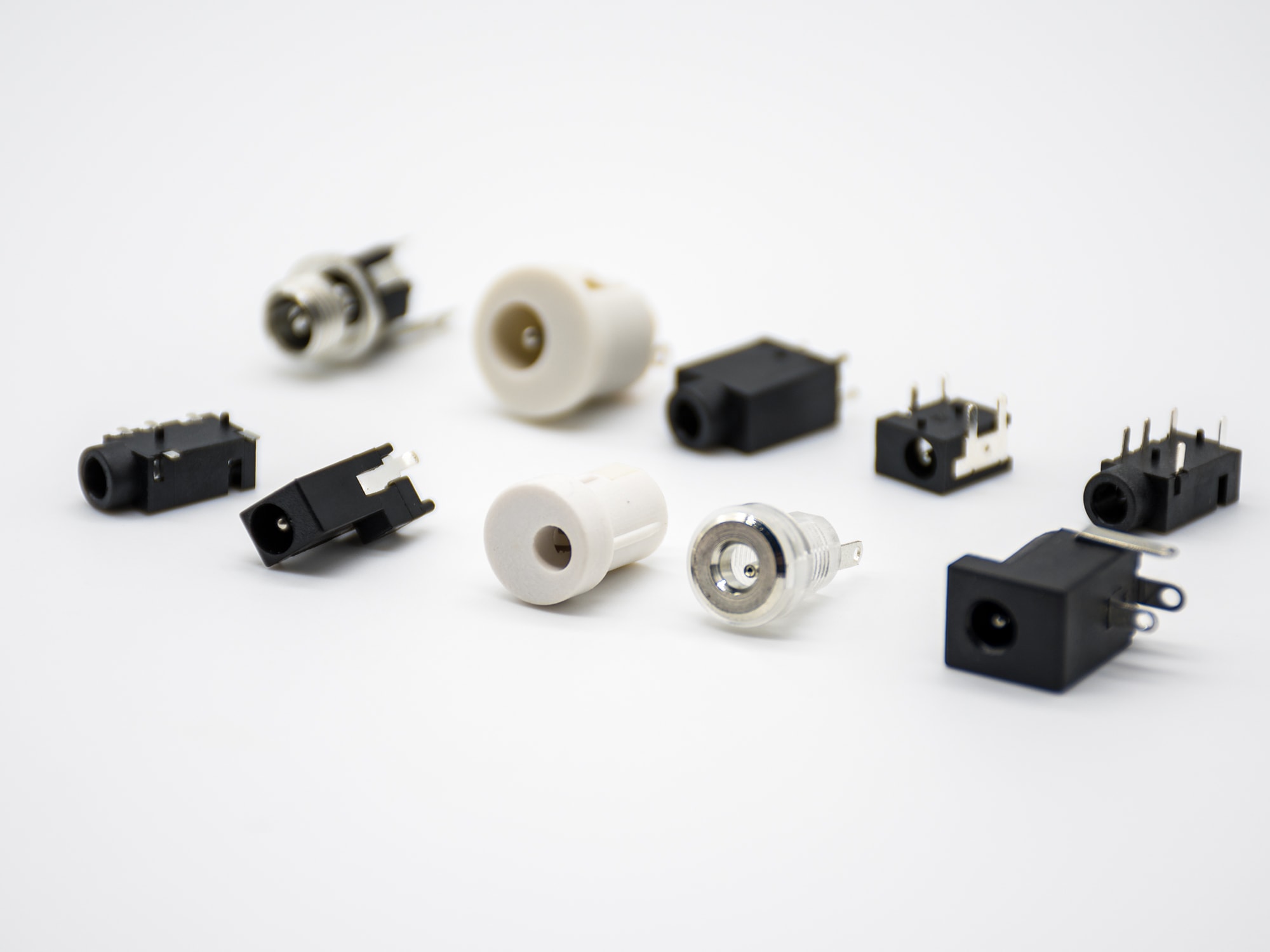
The DC power connector is a type of DC connector that is specifically used to transmit DC power to the device. Compared with other power connectors, they have lower current and voltage ratings. They are mainly used for 12 V DC. They are common low-power electronic devices. These connectors are available in male and female types. Their male pins usually have a cylindrical structure, and their internal and external contacts are separated by insulating materials. Male DC connectors are usually called DC jacks, while female DC connectors are called DC sockets. The DC jack is connected to a wire that flows downward from the DC adapter or battery eliminator. The DC socket is soldered to the circuit board to which the DC socket is to be connected.

DC sockets are usually mounted on the edge of the PCB, so there are no other components to prevent the pins from entering the connector. You can always find the ON/OFF switch and the power indicator LED next to the DC outlet. The DC socket is a simple cylindrical structure, and the two contacts are separated by an insulating structure, but the DC socket is not that simple. Even though DC jacks have only two contacts, most DC jacks have three pins. The outer cylindrical contact is GROUND, and the inner pin is positive.
Although most circuit boards have batteries attached, we can still plug in an external DC adapter to operate the circuit. The three-pin structure of the DC socket is used to separate the GROUND terminal of the battery from the GROND terminal of the DC adapter. The positive terminal of the battery and DC adapter can be connected to PIN 1 of the DC socket. PIN 1 and PIN 2 provide power to the PCB. PIN 3 is where the GROUND of the battery is connected.