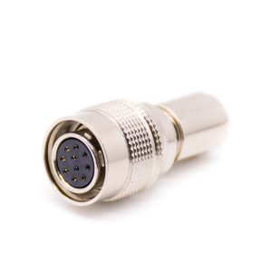
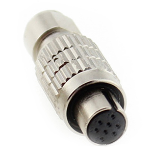
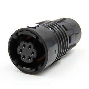
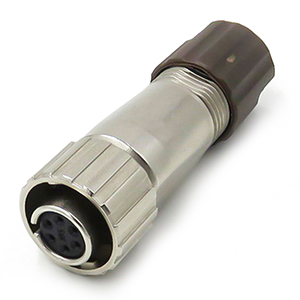
M Series Connectors
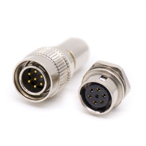
Are lightweight triplestart ratchet coupling type connectors designed for avionics, aerospace, Harsh Environment Connectors, security, motorsport and heavy duty applications.
The Y50 series circular connector family represents a mature, high-density interconnect architecture extensively utilized across aerospace, defense, industrial automation, and rugged marine applications. Engineered with a quick-disconnect bayonet coupling mechanism, these connectors are designed to provide rapid mating and unmating while ensuring robust structural integrity under severe mechanical stress. The entire product lineup is systematically developed to comply with rigorous military and industrial specifications, notably referencing the Chinese military standard GJB101A-97 and cross-referenced with international benchmarks such as MIL-C-26482 and GJB598A-96. By aligning with these standardized design principles, the Y50 series guarantees strict intermateability and performance consistency, making it a reliable choice for engineers specifying components for global deployment.
To satisfy diverse electrical and environmental operating parameters, the Y50 series is segmented into three distinct commercial sub-series:
Evaluating a circular interconnect for mission-critical deployments requires a granular analysis of its operational boundaries under combined electrical, mechanical, and environmental stresses. The Y50 series is engineered to maintain structural and electrical continuity across a broad thermal spectrum, operating reliably from -55 ℃ to +125℃ for standard signal variants, while high-power modifications (such as the Y50DX sub-series) extend this upper threshold to +150℃ to accommodate localized Joule heating from continuous high-current transmission. Mechanically, the precision-machined three-pin bayonet coupling system delivers an enduring mechanical service life exceeding 500 mating cycles. This longevity is fundamentally supported by internal stainless steel wave springs that provide constant axial tension, preventing material fatigue and contact fretting even under severe vibration regimes.
From an electrical perspective, the insulation performance of the Y50 series is defined by its dielectric material composition, typically leveraging high-performance diallyl phthalate (DAP) or polyphenylene sulfide (PPS) inserts. Under standard atmospheric conditions (20℃ ±5℃ , relative humidity ≤80%), the insulation resistance between any pair of contacts, or between any contact and the conductive shell, achieves a minimum threshold of 3000MΩ. However, in field deployments, environmental ingress and atmospheric pressure drops drastically alter these dielectric thresholds. For instance, during high-altitude operations or within low-pressure chambers simulating elevations where atmospheric pressure drops to 4.39KPa(equivalent to an altitude of 20,000 meters), the dielectric withstanding voltage undergoes a mandatory derating to prevent corona discharge and air ionization breakdown. The following comprehensive parametric matrix defines the exact performance limits of the standard Y50 series:
| Performance Parameter | Testing Condition / Environment | Technical Metric / Limit | Engineering Significance |
|---|---|---|---|
| Operating Temperature | Continuous exposure in thermal chambers |
Y50X: -55°C to +125°C Y50DX: -55°C to +150°C |
Defines the physical boundaries before insert polymer material softening or contact plating degradation occurs. |
| Vibration Profile | Three mutually perpendicular axes (Low/High Freq) |
Frequency: 10 Hz ~ 2000 Hz Acceleration: 196 m/s² |
Governs structural suitability for train bogies, multi-axis robotics, and aerospace harmonic environments to prevent electrical chatter. |
| Mechanical Shock | Peak acceleration, half-sine pulse duration |
Acceleration: 490 m/s² Constant Accel: 490 m/s² |
Ensures the internal wave springs and bayonet locking pins survive high-impact drop loads or deceleration spikes without un-mating. |
| Atmospheric Pressure Limits | High-altitude simulation (Low barometric pressure) |
Minimum Pressure: 4.39 KPa (Equivalent to 30,000m altitude) |
Determines the dielectric breakdown threshold. Voltage derating must be enforced at this level due to the lowered insulation properties of thin air. |
| Insulation Resistance | Measured at 500V DC between adjacent contacts/shell |
Normal Temp: ≥ 3000 MΩ (Y50X) Damp Heat: ≥ 20 MΩ |
Ensures trace-to-trace circuit isolation. Prevents catastrophic crosstalk, leakage current, and signal shorts in harsh field operation. |
| Dielectric Withstanding | RMS voltage at sea level (101.33 KPa) vs High altitude |
Sea Level: 1000V ~ 1500V AC At 4.39 KPa: 200V ~ 300V AC |
Defines the peak voltage limit before triggering flashover. Confirms the structural safety factor under transient voltage spikes. |
| Hermetic Ingress Sealing | Differential pressure tracking (Polymer vs Glass matrix) |
Standard Sealed: 0.2 MPa Glass Hermetic (H): ≤ 1×10⁻⁵ Pa·cm³/s |
Guarantees complete environmental isolation. High airtightness blocks harsh moisture or fluid migration paths into vacuum-sealed enclosures. |
| Mechanical Durability | Continuous mating and un-mating cycles at rated torque | Standard Cycles: ≥ 500 cycles | Establishes the lifecycle reliability baseline of the coupling mechanisms and gold-plated surfaces during routine equipment maintenance. |
The longevity of these electrical boundaries is intrinsically tied to the shell’s metallurgical surface treatment. The standard aluminum alloy housings are processed using specialized electroplating or chemical conversion lines. Olive drab chromate over cadmium or zinc-cobalt coatings provides excellent corrosion resistance, easily surpassing the standard 48-hour salt spray benchmark while maintaining structural shielding continuity. For non-magnetic or highly corrosive applications where cosmetic degradation must be avoided, electroless nickel plating is utilized. This plating deposits a highly uniform phosphorus-nickel alloy layer across intricate geometries, including internal threads and bayonet tracks. This precise plating architecture yields a shell-to-shell conductivity that restricts shielding resistance to ≤5MΩ, effectively forming a highly conductive Faraday cage around the internal contact layout to mitigate electromagnetic interference (EMI).
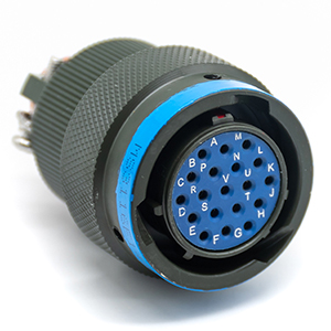
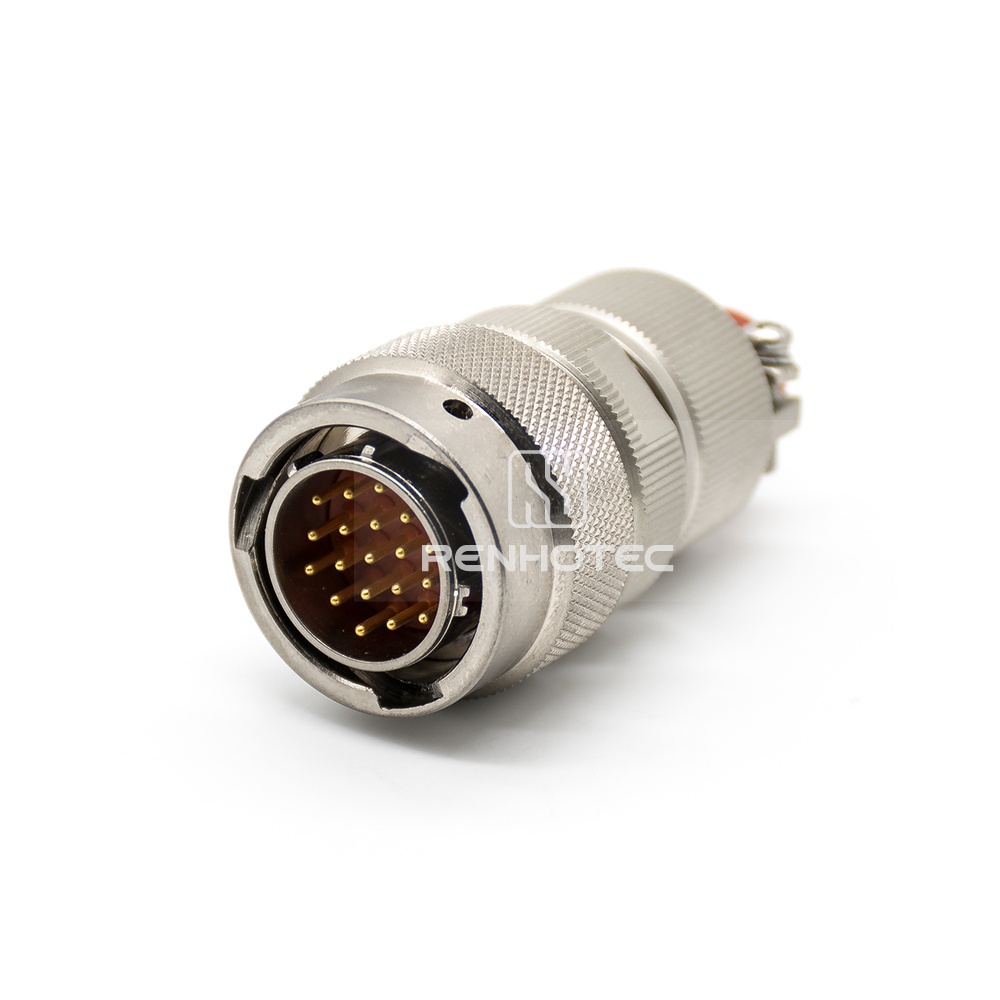
Selecting the optimal geometric envelope for high-reliability packaging requires a precise correlation between shell size dimensions and internal contact density. In the Y50 interconnect architecture, the shell size designations (ranging systematically from 08, 10, 12, 14, 16, 18, 20, 22, to 24 and larger custom scales) represent the nominal outer diameter of the mating receptacle barrel in millimeters. Each incremental step in shell size expands the available insert surface area, allowing engineers to scale pin counts from a minimal 2-contact layout in size 08 up to high-density 61-contact arrays in size 24. This volumetric scaling factor dictates not only the panel cutout profile but also the structural clearance needed for adjacent connectors in multi-port hardware interfaces.
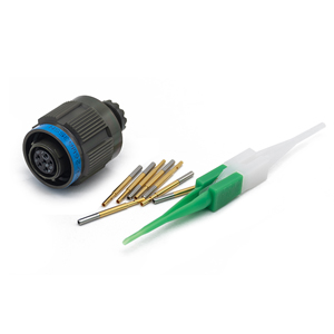
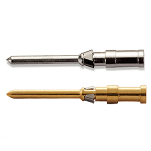
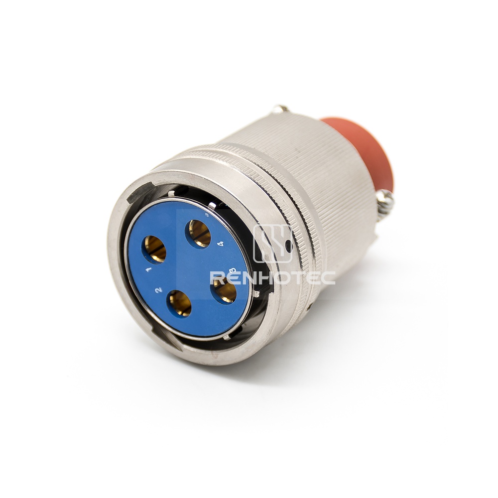
The electrical capacity of each contact arrangement is strictly governed by the physical diameter of the machined copper alloy pins. The Y50 series utilizes three standard pin diameters to partition signal and power lines safely: 1.0mm, 1.5mm, and 2.0mm, with heavier industrial variants integrating 3.0mm and larger terminations for massive power routing. As contact diameter increases, the current-carrying capability scales up, but the maximum achievable pin density within a single shell size decreases proportionally due to dielectric spacing constraints required to prevent high-voltage creeping. To prevent mis-mating in dense panels where multiple Y50 units share identical shell sizes and pin layouts, the system incorporates five distinct hardware orientation keyways: N (Normal), W, X, Y, and Z. Rotating the internal insert assembly relative to the master keyway at predetermined angular intervals ensures that only matching plug-and-receptacle pairs can physically engage, protecting sensitive internal sub-circuits from destructive cross-voltage conditions.
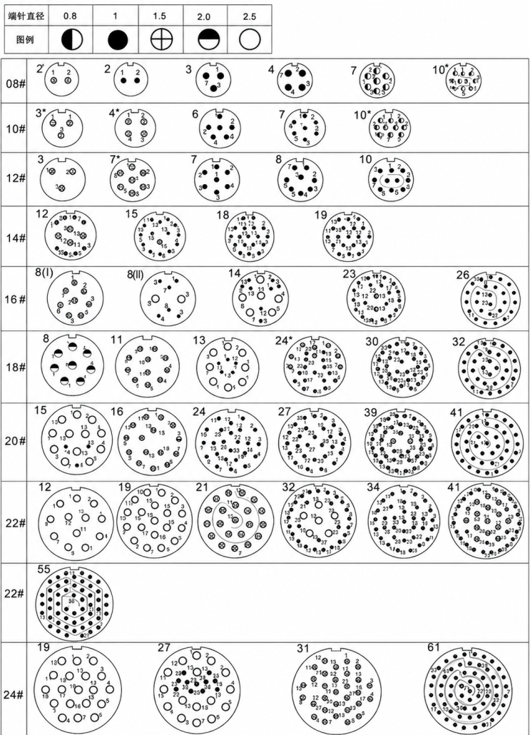
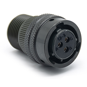
Y50X Contact Layout
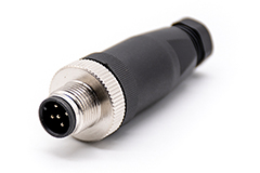
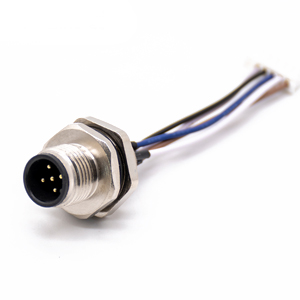
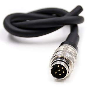
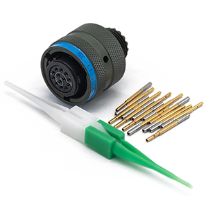
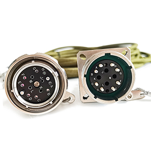
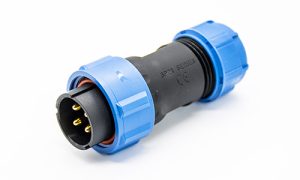
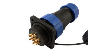
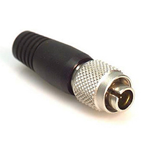
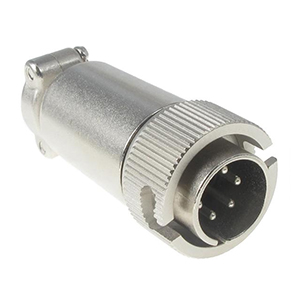
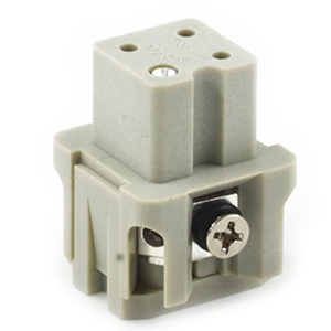
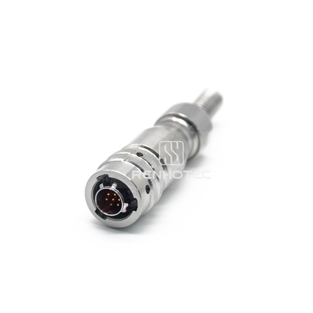
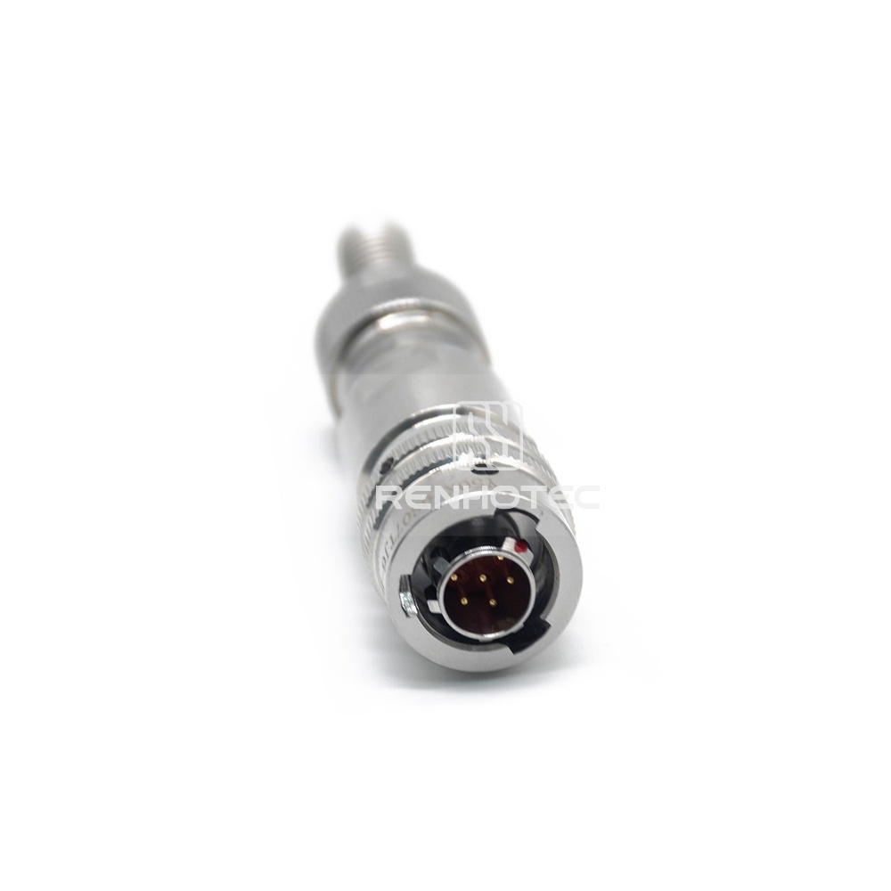
Within the Y50 framework, the plug (designated by the identifier “T”) serves as the mobile component attached to the cable harness, housing the coupling ring and the primary internal wave spring washer assemblies. Conversely, the receptacle (designated by the identifier “Z”) acts as the static panel-mounted interface that accepts the plug’s interlocking mechanism. The mechanical synchronization between these two components relies on a precise three-pin bayonet design. As the plug sleeve is rotated 120℃ clockwise along the machined ramps of the receptacle shell, the internal stainless steel pins glide into detent positions, yielding an audible click that confirms full electrical and environmental mating without the risk of backing off under low-frequency harmonic resonance.
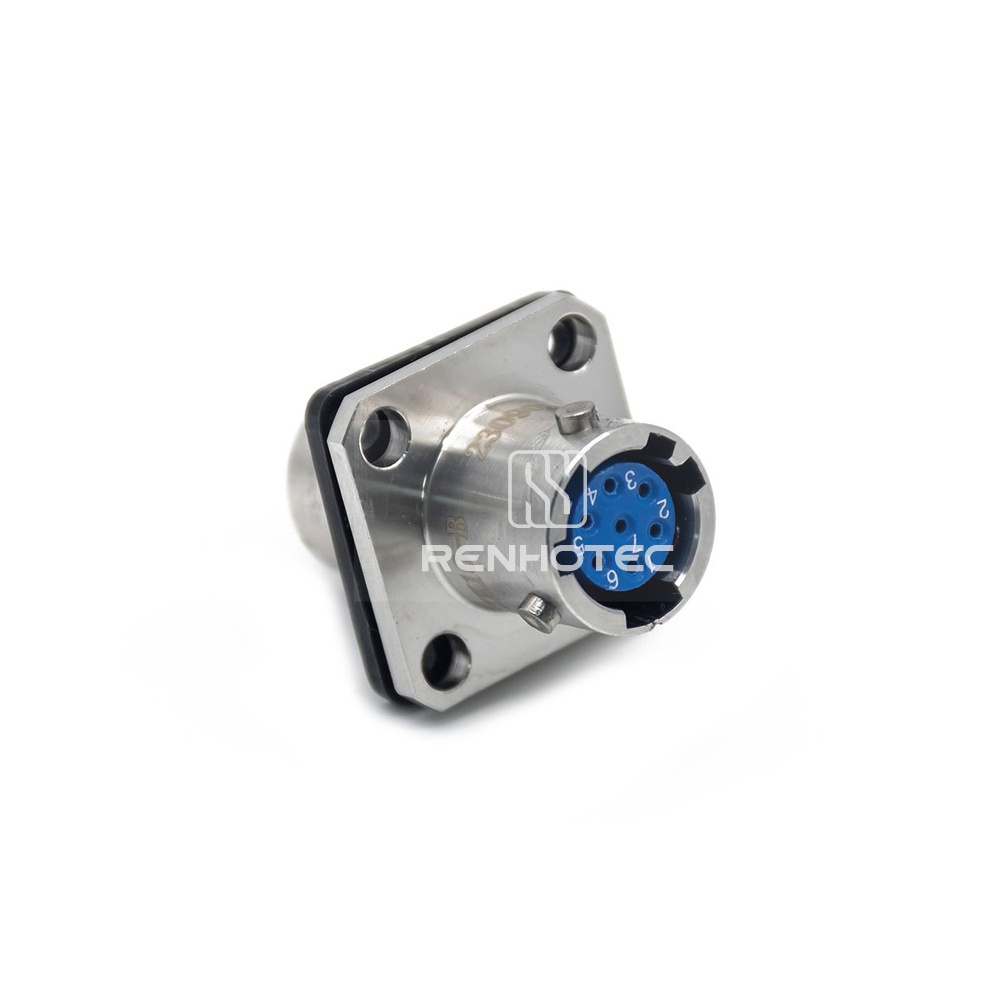
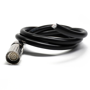
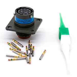
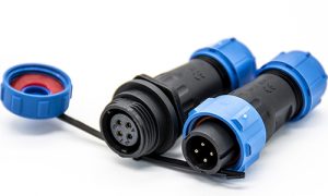
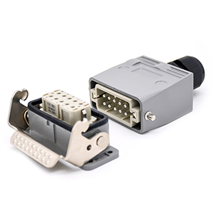
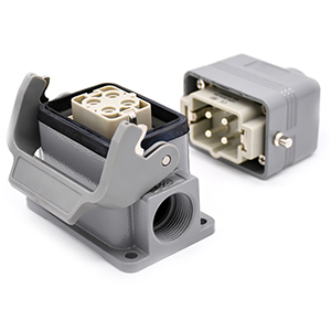
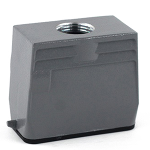
Beyond the basic locking interface, the physical shell configurations of both plugs and receptacles must be systematically tailored to match the specific structural limits of the enclosure. Receptacles are deployed in three primary mounting footprints to maintain enclosure integrity: box-mount square flange (Type Z), wall-mount square flange with backend threads, and single-hole jam nut rear-mount configurations. Plugs are customized through a selection of backend hardware and cable clamps designed to manage cable strain and shield continuity. These backshells are critical to preventing mechanical stress from transferring directly to the delicate soldered or crimped wire terminations inside the insert. The structural options for both interfaces are contrasted below to aid in system routing decisions:
Mitigating supply chain volatility in international engineering projects necessitates the strategic integration of qualified second-source components designed to provide drop-in mechanical intermateability and parametric alignment with established international standards. The Y50 series circular connector is architected specifically to provide a seamless cross-reference alternative to dominant global standards, most notably the Amphenol PT Series, Souriau 851 Series, and ITT Cannon KPT series, all of which conform to the legacy MIL-DTL-26482 (formerly MIL-C-26482) Series I specification. Because the Y50 series shares identical three-pin bayonet coupling geometry, shell diameters, mounting hole spatial pitches, and insert arrangements with these international product lines, procurement teams and systems integrators can execute direct, bill-of-materials (BOM) level substitutions without requiring panel redesigns or wire harness re-tooling.
When evaluating a Y50 series connector as a drop-in replacement for tier-one global brands, engineering compliance must be validated across three critical vectors: physical envelope form-factor, insert layout correlation, and environmental durability limits. From a mechanical perspective, a Y50 shell size 14 possesses the exact same panel cutout diameter and flange mounting hole center-to-center measurements as a MIL-DTL-26482 size 14 receptacle, ensuring that the structural sealing integrity of the bulkhead is preserved. Electrically, the contact layouts map directly to international designations (e.g., the Y50-1419 layout corresponds precisely to the 14-19 insert arrangement featuring 19 size-20 contacts). To assist procurement managers and components engineers in establishing formal cross-reference protocols, the following brand mapping matrix outlines standard direct-replacement configurations:
| OEM Standard P/N (MIL-DTL-26482 / PT) | Shell Size & Layout | Contact Gender & Type | Shell Finish & Plating Match |
|---|---|---|---|
| PT02E-12-10P | Size 12, 10 Pins | Pin (J), Solder | Olive Drab Anodized (L) |
| PT06A-14-19S | Size 14, 19 Pins | Socket (K), Solder | Electroless Nickel (P1) |
| MS3112E-16-26P | Size 16, 26 Pins | Pin (J), Solder | Bright Nickel (P2) |
| PT02A-18-32S | Size 18, 32 Pins | Socket (K), Solder | Olive Drab Anodized (L) |
| MS3116F-22-55P | Size 22, 55 Pins | Pin (J), Solder | Olive Drab Anodized (L) |
| PT06E-24-61S | Size 24, 61 Pins | Socket (K), Solder | Electroless Nickel (P1) |
To ensure long-term field survivability and eliminate procurement configuration errors, component engineers should execute a systematic three-stage selection matrix when specifying a Y50 component from the factory catalog:
Aggregate the aggregate operational current per channel and total circuit counts. If routing sensitive low-voltage sensor lines (e.g., 3A to 5A), standard Φ0.8mm or Φ1.0mm pins within the Y50X line are optimal. For power supply lines requiring up to 50A, 100A, or higher continuous loads, transition directly to a Y50DX variant to leverage enlarged copper-alloy contacts (Φ3.0mm to Φ12.0mm) that prevent catastrophic thermal overload.
Measure the exact panel thickness and spatial envelope on the chassis face. Select the smallest shell size index (from 08 up to 24) that comfortably encompasses your chosen contact arrangement. Determine whether the static end requires a standard four-hole square flange (best for distributing heavy cable-weight torque) or a single-hole jam nut rear mount (best for tight-packed, multi-port control boxes).
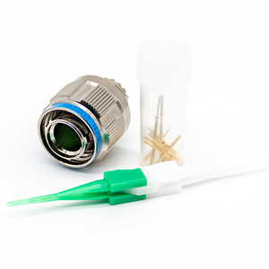
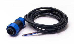
Define the moisture, fluid, and electromagnetic interference (EMI) profile of the deployment site. For severe fluid-exposure zones, specify a “Welded and Rubber Sealed” termination or a “Glass Sintered Hermetic” configuration to maintain a rigid 0.2MΩ hydraulic barrier. Select an appropriate backshell or cable clamp—such as a straight shielded clamp for 360℃ grounding or a 90℃ elbow to divert pathing around tight structural corners.
By working through this structured decision framework, engineering groups avoid the costly pitfalls of component over-specification—such as implementing an unnecessarily bulky power housing for low-current instrumentation lines—while simultaneously ensuring that the chosen assembly meets or exceeds the precise environmental limits required by the application.
For senior design architects evaluating long-term infrastructure deployments, selecting between the Y50 framework and the legacy MIL-DTL-5015 (commonly referred to as the 5015 series) involves navigating fundamental tradeoffs in coupling mechanics, structural density, and harmonic vibration resistance. The primary structural divergence lies within their respective locking systems: the Y50 utilizes a 120℃ rapid-mating three-pin bayonet mechanism, whereas the standard MIL-DTL-5015 is engineered around a heavy-duty, multi-turn fine-thread coupling sleeve. Under operational conditions characterized by severe low-frequency vibration, threaded assemblies without secondary locking wires are prone to backing off due to friction reduction, whereas the Y50 bayonet pin system sits firmly inside machined detent ramps under constant axial tension from an internal stainless steel wave spring, providing superior resistance to shock-induced backing off.
From a spatial packaging and high-density signal perspective, the Y50 series delivers a significantly optimized envelope profile compared to the bulky footprint typical of the 5015 series. The internal contact density of a Y50 series connector allows it to accommodate up to 61 discrete signal lines within a shell size 24 envelope. Conversely, a comparable MIL-DTL-5015 housing with similar pin arrangements requires a much larger physical envelope and thicker shell walls, leading to increased weight penalties on a multi-port bulkhead panel. However, the heavy-walled design of the 5015 series gives it an advantage in brute-force mechanical survivability and high-voltage isolation limits. To assist layout engineers in conducting exact component evaluations, the following architectural matrix contrasts the standard performance limits of both series:
| Architectural Metric | Y50 Series Circular Connector | MIL-DTL-5015 Series Standard | Engineering Layout Significance |
|---|---|---|---|
| Coupling Mechanism | Quick-disconnect 120° 3-pin bayonet | Multi-turn fine threaded (M or unified) | Governs installation speed and maintenance turnaround times. |
| Vibration Tolerance | 10Hz to 2000Hz, acceleration 196 m/s² | Variable; susceptible to harmonic loosening | Determines suitability for bogies and multi-axis robotics. |
| Volumetric Density | High density (Up to 61 signal lines in size 24) | Low to medium density (Thicker barriers) | Directly impacts total panel space and chassis weight. |
| Voltage Limits (AC) | 1000V to 1500V under normal conditions | Can exceed 2000V depending on insert class | Defines the physical dielectric barrier thickness requirements. |
| Current Limits (A) | Up to 250A in dedicated Y50DX variants | Up to 225A (Size 0 contacts) | Sets thermal boundaries under full continuous loads. |
| Mating Cycles Rating | ≥ 500 Cycles | ≥ 100 or ≥ 500 depending on finish | Impacts the operational longevity of diagnostic connections. |
The decision to implement either interconnect architecture ultimately hinges on the specific space-to-power parameters of the target application. When the system design dictates high-density multi-channel signal routing (such as RS-422 networks, encoder lines, or multi-sensor processing trunks) alongside tight spatial limitations, the Y50 series serves as the preferred standard. It provides an efficient form factor that reduces system footprint. Alternatively, the 5015 series remains viable primarily for stationary, legacy heavy-power drops where ample installation clearance exists and weight parameters are unconstrained.
To ensure your equipment runs smoothly without unexpected downtime, it is important to monitor the health of your cable connections. In high-vibration applications like factory robotics or moving vehicles, the most common issue is “fretting wear” on the pins. This happens when continuous shaking causes the plug and receptacle to rub against each other, eventually wearing away the protective gold plating. When this layer is gone, the underlying copper oxidizes, causing unstable signals or data packet loss. To prevent this, maintenance teams should regularly check the resistance of the pins using a standard meter to ensure it stays within the safe factory limit (≤5mΩ for standard signal pins).
Another frequent issue is water or fluid leakage caused by pulling or bending cables too tightly around sharp corners. This high stress creates micro-gaps around the rubber seals, allowing moisture or industrial coolants to creep inside the connector. Once fluid gets in, it shorts out adjacent pins and drops the insulation safety baseline. To quickly find and fix these issues in the field, technicians can use the following straightforward checklist:
| Observed System Symptom | Potential Root Structural Failure | Immediate Field Correction Action | Long-Term Preventative Protocol |
|---|---|---|---|
| Unstable data or signal drops when machine moves | Worn-out gold plating on pins due to vibration; loose locking spring. | Replace the plug; make sure you twist the coupling ring until it clicks completely. | Specify hard-gold electroplating over nickel underplates (≥ 1.27µm). |
| Complete signal short or wet pins inside | Liquid leaked through the back of the cable because it was bent too tightly. | Clean inside with electronics spray; dry it completely; replace torn seals. | Upgrade to our factory-molded “Welded & Rubber Sealed” (焊接胶封) cable versions. |
| Visible sparks or error codes at high altitudes | Thin air at high altitudes lowers the insulation gap between pins. | Reduce the system running voltage to a safe limit (300V AC) under low-pressure conditions. | Implement vacuum-rated glass-sintered hermetic enclosures with potted backends. |
| The plug is very stiff and hard to lock | The alignment slots are bent, or there is dirt/sand stuck in the tracking grooves. | Spray out the debris with clean solvent; check if the panel mounting alignment is straight. | Enforce the use of protective dust caps (Type F) whenever assemblies remain unmated. |
By keeping up with these simple checks—like keeping connectors capped and avoiding tight cable bends—you can significantly extend the lifespan of your systems. If you run into severe or repeating issues that a quick cleaning cannot fix, do not hesitate to contact our engineering team.
Answer: Yes. The standard Y50 series utilizes the exact same three-pin bayonet locking geometries, master keyway clocking angles, and contact spacing layout configurations as specified in the legacy MIL-DTL-26482 Series I framework. This structural compatibility ensures complete direct, plug-to-receptacle intermateability and drop-in component footprint compliance with an Amphenol PT06 or PT02 assembly without requiring panel re-drilling or wire harness redesigns.
Answer: The primary differences center on dimensional standards and contact power handling. The Y50X series is engineered around metric thread dimensions and high-density layouts optimized for lower-current signals (3A to 5A) in transit and automation lines. The Y50DX sub-family integrates heavy-duty, large-diameter copper-alloy contacts (∅ 3.0mm to ∅ 12.0mm) built to deliver continuous power transmission up to 250A. The Y50EX sub-family adheres strictly to imperial dimensioning and unified thread standards, making it the primary choice for global procurement networks matching legacy Western equipment profiles.
Answer: For marine environments characterized by high salinity and humidity, we recommend specifying the Olive Drab Cadmium or Olive Drab Anodized finish (denoted by the code L). This coating provides a robust defensive layer capable of surviving continuous 500-hour salt spray testing without base-metal degradation. For applications requiring strict environmental compliance, our Electroless Nickel (P1) finish serves as an excellent lead-free alternative for moderate marine exposures.
Answer: Transitioning from standard rubber-sealed inserts to a glass-sintered hermetic receptacle (Type H) swaps the polymer compound for a solid compressed glass matrix. This material change elevates the physical pressure resistance, allowing the bulkhead interface to maintain an airtight seal with a gas leakage rate of ≤ 1×10⁻⁵ Pa·cm³/s under high-pressure boundaries. However, it requires a derating of continuous current limits because glass has lower thermal dissipation properties than standard copper-alloy/polymer inserts.
Answer: To prevent mechanical stress from pulling contacts out of alignment or fracturing internal solder joints, the assembly layout must maintain a static bend radius of at least 6 times the total outside diameter (≤ 6×∅) of the aggregate cable bundle. In high-vibration dynamic environments, this margin should be extended to ≤ 10×∅, paired with a straight or 90° elbow compression backshell to provide robust strain relief.
Answer: Contact resistance is the most reliable indicator of internal contact health. When a connector is subjected to constant machine harmonics, micro-vibrational fretting can wear away the external gold plating layer, causing the underlying copper to oxidize and spike resistance past the standard ≤ 5mΩ threshold. Tracking this parameter lets field service crews isolate and replace worn plugs during scheduled maintenance windows before an open-circuit failure triggers system downtime.

As a Product Manager at Renhotec Group (est. 2008), I specialize in providing deep technical insights into connectors, cables, and custom electronic components. Renhotec is a global leader in interconnect solutions, dedicated to manufacturing high-standard products for diverse industries as your trusted technical partner.